

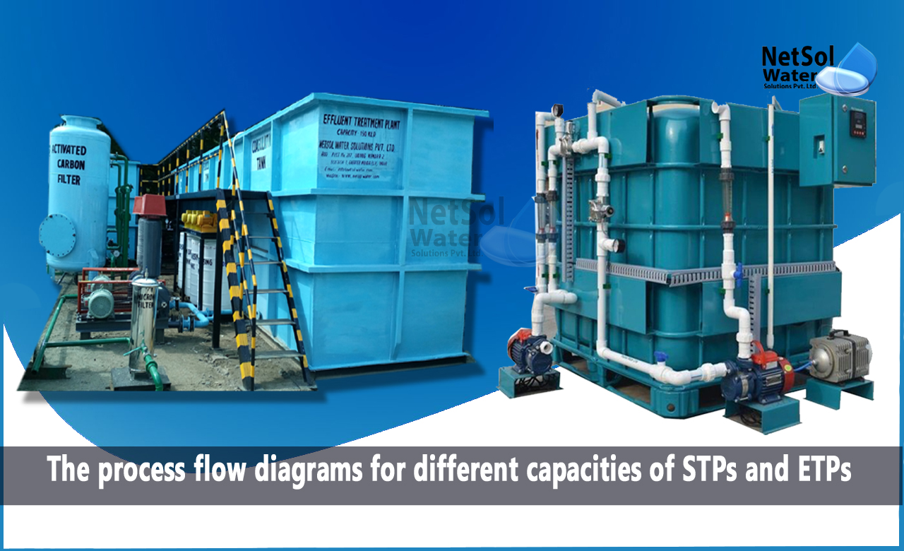
Process flow diagrams for different capacities of STPs and ETPs
Sewage treatment plants (STPs) and Effluent treatment plants (ETPs) play a crucial role in treating wastewater generated from households and industries. Process flow diagrams (PFDs) are graphical representations of the process flow and equipment layout of STPs and ETPs.
Here we will discuss the process flow diagrams for different capacities of STPs and ETPs.
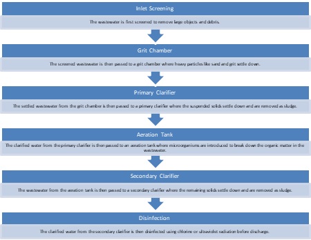
Process Flow Diagram for 100 KLD STP:
Some of the common components of a process flow diagram for 100 KLD STP are:
1. Bar screen chamber:
A device that removes large solids and debris from the incoming sewage.
2. Equalization tank:
A tank that collects and stores the sewage and regulates its flow and characteristics before entering the treatment process.
3. SBR tank:
A tank that operates in time rather than in space and performs five steps: fill, react, settle, decant, and idle. It is one of the options for treating municipal sewage using biological methods.
4. Treated water holding chamber:
A chamber that stores the treated effluent before reuse or discharge.
5. Tertiary treatment filters:
Filters that provide additional polishing of the treated effluent to meet the desired quality standards.
6. Filter press:
A device that separates and dewaters the sludge produced by the treatment process
The process flow diagram for a 100 KLD STP consists of the following stages:
Process Flow Diagram for 50 KLD, 10 KLD, and 25 KLD STPs:
The process flow diagrams for 50 KLD, 10 KLD, and 25 KLD STPs are similar to the 100 KLD STP, with some differences in the size of equipment and the capacity of the pumps and motors. But, the general process flow remains the same.
However, some of the common components of a process flow diagram for 10 KLD STP are:
1. Bar screen chamber: A device that removes large solids and debris from the incoming sewage.
2. Equalization tank: A tank that collects and stores the sewage and regulates its flow and characteristics before entering the treatment process.
3. MBBR tank: A tank that uses moving bed biofilm reactor (MBBR) technology to treat municipal sewage using biological methods. It consists of plastic carriers that provide a large surface area for biofilm growth and aeration system that supplies oxygen and mixes the carriers.
4. Treated water holding chamber: A chamber that stores the treated effluent before reuse or discharge.
5. Tertiary treatment filters: Filters that provide additional polishing of the treated effluent to meet the desired quality standards.
6. Filter press: A device that separates and dewaters the sludge produced by the treatment process
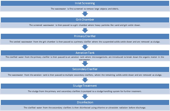
Process Flow Diagram for 1000 KLD STP:
Some of the common components of a process flow diagram for 1000 KLD STP are:
1. Bar screen chamber: A device that removes large solids and debris from the incoming sewage.
2. Oil and grease trap: A device that separates oil and grease from the sewage by gravity separation.
3. Collection tank: A tank that collects and stores the sewage before pumping it to the treatment process.
4. Aeration tank: A tank that provides oxygen and mixing to the sewage for biological treatment using activated sludge process (ASP).
5. Clarifier: A tank that separates the treated effluent from the activated sludge by gravity settling.
6. Sludge holding tank: A tank that stores the excess sludge produced by the treatment process before dewatering.
7. Filter press: A device that separates and dewaters the sludge using pressure filtration.
8. Treated water holding chamber: A chamber that stores the treated effluent before reuse or discharge.
9. Chlorine contact tank: A tank that disinfects the treated effluent using chlorine before reuse or discharge
The process flow diagram for a 1000 KLD STP is similar to that of a 100 KLD STP, with some differences in the number and size of equipment. The process flow diagram for a 1000 KLD STP consists of the following stages:
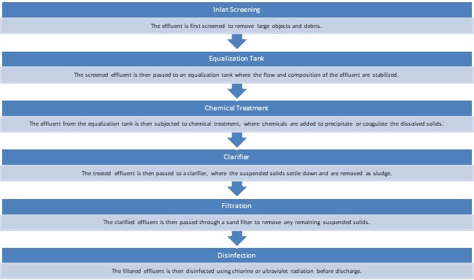
Process Flow Diagram for ETPs:
The process flow diagram for ETPs is similar to that of STPs, with some differences in the type of wastewater treated and the process used. The process flow diagram for 10 KLD, 50 KLD, and 100 KLD ETPs consists of the following stages:
1. Screen chamber:
A device that removes large solids and debris from the incoming effluent.
2. Oil and grease trap:
A device that separates oil and grease from the effluent by gravity separation.
3. Equalization tank:
A tank that collects and stores the effluent and regulates its flow and characteristics before entering the treatment process.
4. Flash mixer:
A device that mixes the effluent with coagulants and flocculants for chemical treatment.
5. Clariflocculator:
A device that combines clarification and flocculation in one unit. It removes suspended solids and organic matter from the effluent by gravity settling.
6. Aeration tank:
A tank that provides oxygen and mixing to the effluent for biological treatment using moving bed biofilm reactor (MBBR) technology. It consists of plastic carriers that provide a large surface area for biofilm growth and aeration system that supplies oxygen and mixes the carriers.
7. Secondary clarifier:
A tank that separates the treated effluent from the excess biomass by gravity settling.
8. Sludge holding tank:
A tank that stores the excess sludge produced by the treatment process before dewatering.
9. Filter press:
A device that separates and dewaters the sludge using pressure filtration.
10. Treated water holding chamber:
A chamber that stores the treated effluent before reuse or discharge.
11. Chlorine contact tank:
A tank that disinfects the treated effluent using chlorine before reuse or discharge.
Summary:
Process flow diagrams are essential tools that help to understand the various stages involved in wastewater treatment. The process flow diagrams for different capacities of STPs and ETPs provide a clear understanding of the processes involved in treating wastewater. These diagrams also help in the proper selection and sizing of equipment and in the design of efficient wastewater treatment systems. Proper design and operation of STPs and ETPs are crucial to ensure the safe discharge of treated wastewater and to protect the environment.
Leading manufacturer of sewage treatment plants in India.
Netsol Water is the leading manufacturer, supplier, and exporter of a quality selection of water treatment, and wastewater treatment products in India, by using advanced sewage treatment methods.
RO plants, water softeners, ETPs, STPs, DM plants, AMC, O&M, Ultra filtration, UV, Ozonation, ZLD plants, Anoxic tanks, and other goods and services are available from us. We also provide services to businesses in sectors including automotive, pharmaceutical, textile, pulp & paper, beverages, refineries, schools, hospitals, office buildings, and hotels, among others.
Call us at +91 9650608473 or email at enquiry@netsolwater.com for further information.