
Case Study: Installed 3000 LPH RO Plant at Deepchand Arya Industry, Dadri
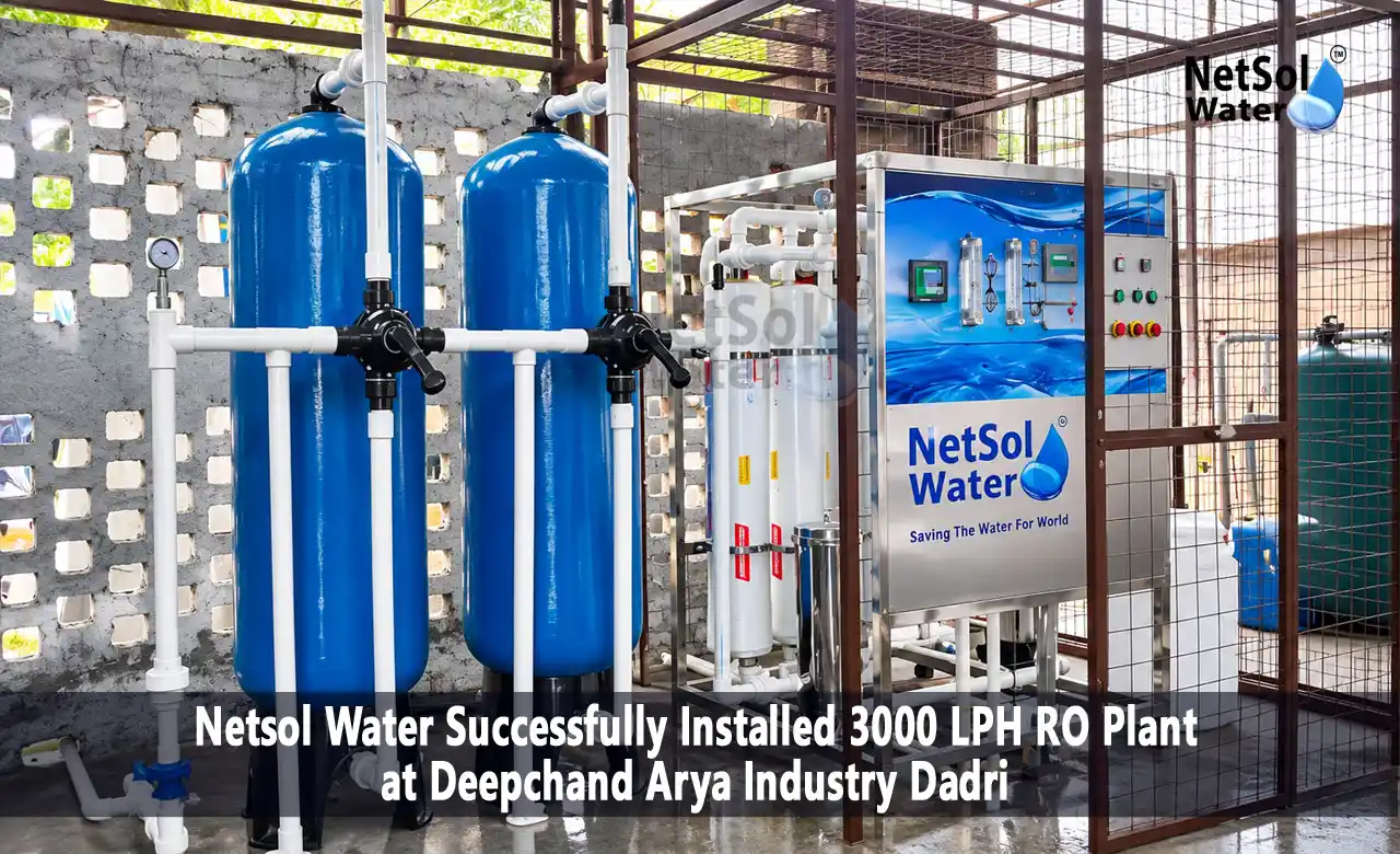
In 2026, Netsol Water installed a 3000 LPH industrial RO plant at Deepchand Arya Industry in Dadri, Uttar Pradesh. This groundwater treatment plant takes in water with a TDS of 2200 mg/L. Treated water measures 90 mg/L. It runs at 70% recovery, so about 70% of the feed becomes permeate and 30% leaves as reject.
This case study explains what we installed, how each stage of the treatment train works and what the numbers mean. It also covers the hardest part of the job, which came from the building and not the water: the equipment had to go to the top floor.
As an industrial RO plant manufacturer, we try to document our projects with recorded values only. Where we did not record a value for this case study, such as pump rating or operating pressure, we have left it out instead of guessing.
Client Background and Project Location
Deepchand Arya Industry is located in Dadri, in the Gautam Buddha Nagar district of Uttar Pradesh, close to Delhi NCR. We installed this industrial RO plant in Dadri for a site that depends on borewell water. Groundwater quality changes a lot from one borewell to the next in this region, and the only reliable way to know what you are treating is to test it. Here, the raw water TDS came in at 2200 mg/L.
This page focuses on the water treatment plant itself. We have not described the client’s own business activity, because it is not needed to understand the design.
Project Requirement and Water Treatment Challenge
The client needed an industrial water purification system that could turn borewell water into drinking water. At 2200 mg/L TDS, filtration alone cannot do that job. Sand and carbon filters remove suspended particles, chlorine and some organic matter, but they cannot remove dissolved salts. Reverse osmosis can.
Two separate problems came with the project. The first was treatment. The plant had to bring TDS down sharply and protect its membranes from chlorine damage on the way. The second was logistics. The plant equipment had to be shifted to the top floor, which affected how we planned the installation.
Raw Water Quality and Treatment Objectives
TDS stands for total dissolved solids. It is the combined amount of dissolved minerals and salts in water, measured in milligrams per litre (mg/L). The raw groundwater at this site measured 2200 mg/L.
This case study uses the recorded TDS values. We make no statements about other raw water parameters such as hardness, iron or silica.
The treatment objectives were clear:
1. Reduce TDS from 2200 mg/L to a much lower level in the treated water.
2. Keep chlorine away from the RO membranes.
3. Run at 70% recovery with a 30% reject stream.
4. Install the plant on the top floor within a short site schedule.
Technical Specifications of the 3000 LPH Industrial RO Plant
| Parameter | Detail |
|---|---|
| Client | Deepchand Arya Industry |
| Location | Dadri, Uttar Pradesh, India |
| Installation Year | 2026 |
| Plant Type | Industrial Reverse Osmosis (RO) Plant |
| Capacity | 3000 LPH (Feed Water) |
| Theoretical Permeate Flow | 2100 LPH at 70% recovery |
| Theoretical Reject Flow | 900 LPH at 30% reject |
| Raw Water Source | Groundwater |
| Raw Water TDS | 2200 mg/L |
| Treated Water TDS | 90 mg/L |
| RO Membranes | 6 LG Membranes |
| Plant Construction | MSFRP |
| Application | Drinking Water |
| Installation Duration | 3 Days |
Working Process of the Industrial RO Plant
The plant follows the usual order for a groundwater treatment plant: pretreat first, then desalinate. Each stage protects the one after it.
1. Raw Water Supply
The raw water pump delivers groundwater from the source into the plant. Everything downstream depends on a steady supply, because the high-pressure pump and the membranes should not run dry or starve.
2. Chlorine Dosing
In this plant, chlorine dosing sits before the pretreatment stages. Chlorine helps control microbial growth and oxidises some dissolved impurities in the feed water, which keeps the filters cleaner. The exact dosing arrangement and chemical dose are not covered in this case study.
Chlorine control matters because conventional RO membranes are chlorine sensitive. Free chlorine that reaches a thin-film composite membrane can damage it permanently, and salt rejection drops. So any residual chlorine has to be removed before the water reaches the membranes. For the exact chlorine tolerance of the membranes, always check the manufacturer’s data sheet.
3. Pressure Sand Filtration
The pressure sand filter removes suspended solids and turbidity. Without it, silt and fine particles would load the later filters and foul the membrane surface. Filter media details are not part of this record.
4. Activated Carbon Filtration
The activated carbon filter takes out residual chlorine by adsorption. It also reduces some organic matter and odour. In this plant, it is the stage that makes the earlier chlorine dosing safe for the membranes. Operators should test for residual chlorine after this stage, because carbon beds wear out over time.
5. Micron Filtration
The micron filter is a cartridge stage that catches fine particles that slipped past the sand and carbon filters. It acts as the last safety net before the high-pressure pump and membranes. Operators replace the cartridges when the pressure drop across them rises.
6. High-Pressure Pumping
Water does not pass through an RO membrane on its own. The high-pressure pump raises the feed pressure above the osmotic pressure of the water, which pushes water through the membrane and leaves most dissolved salts behind. We have not listed the operating pressure for this plant.
7. RO Membrane Treatment
Six LG RO membranes do the actual desalination. Each LG RO membrane is semipermeable. Water molecules pass through, while most dissolved salts stay on the feed side and leave as reject. The result is two streams: low-TDS permeate and a concentrated reject stream.
Understanding 70% Permeate and 30% Reject Ratio
Recovery is the share of feed water that comes out as permeate. This plant is designed for 70% recovery, so the reject share is 30%.
The 3000 LPH rating is feed-water capacity. It is not the amount of drinking water the plant delivers. That is a common point of confusion when people compare plant quotes, so here is the calculation:
1. Permeate flow: 3000 LPH x 0.70 = 2100 LPH
2. Reject flow: 3000 LPH x 0.30 = 900 LPH
3. Check: 2100 + 900 = 3000 LPH
These are theoretical design figures. Actual flow changes with feed temperature, feed TDS, operating pressure, membrane age and fouling. Cold feed water or a dirty pretreatment stage can lower permeate output.
The reject stream is more concentrated than the feed, because the salts the membrane held back leave through it. A simple mass balance, using 2200 mg/L feed and 90 mg/L permeate, puts reject TDS at roughly 7,100 mg/L. This is an estimate, not a measured value from the site. It does show why reject water needs a plan for use or disposal.
Industrial RO Plant Installation Process at Deepchand Arya Industry
The industrial RO plant installation took three days, which is a compact schedule for a plant with this many stages.
We have not published a day-by-day site log, so we will not invent one. In general, any RO installation follows the same order: place the skid and vessels, connect the raw water and treated water piping, complete electrical connections, load and flush the media, install the membranes and commission the plant. Commissioning checks flow, pressure and treated water TDS before handover.
The main constraint on this site was the location.
Major Installation Challenge: Shifting the RO Plant to the Top Floor
The main installation challenge was shifting the RO plant equipment to the top floor. Anyone who has carried heavy equipment up a building knows the problems. Stairs are narrow, turns are tight and vessels are awkward to handle.
A top-floor installation also adds questions that a ground-level plant does not raise:
1. Can the floor carry the weight of a plant full of water and media?
2. How will raw water reach the plant, and where will the reject go?
3. Where will filters be serviced, and how will media be replaced later?
We did not record the specific handling methods used on this site, so we do not describe them. This was the main difficulty on the job, and the whole installation still took three days.
If you are planning a similar rooftop or upper-floor plant, raise access routes and floor loading with your RO supplier before the plant is built, not after it arrives.
Water Quality Results and Treatment Performance
The recorded TDS values were 2200 mg/L in the raw water and 90 mg/L in the treated water.
TDS reduction = (2200 minus 90) divided by 2200 x 100 = 2110 / 2200 x 100, which is approximately 95.9%.
That is a strong reduction in dissolved solids. It should be read for what it is: a TDS figure. It does not mean every contaminant was removed, and it does not describe bacteria, pesticides, fluoride, nitrate or heavy metals.
For drinking water, TDS is only one parameter. We do not claim that this water meets BIS IS 10500 or any other standard here. That needs a complete laboratory report from an accredited lab, and we recommend testing the treated water that way before relying on any plant for drinking.
Benefits of the Installed Industrial RO Plant
The recorded project data supports these benefits:
1. A large drop in TDS, from 2200 mg/L to 90 mg/L, in water meant for drinking use.
2. A theoretical 2100 LPH of permeate from 3000 LPH of feed water.
3. Pretreatment that protects the membranes, including chlorine control ahead of the RO stage.
4. A compact plant that was installed in three days, even with a top-floor location.
5. Six LG RO membranes for the desalination stage.
We do not claim savings, payback or uptime figures here, because none were recorded for this project.
Project Installation Video
3000 LPH Industrial RO Plant Installation at Deepchand Arya Industry, Dadri
Watch the actual project video here:
The video comes from this installation. Read the process section above first, then watch the video and see how the plant equipment is arranged on site. It is a useful way to see what an industrial RO plant looks like in the real world, instead of in a diagram.
Why Choose Netsol Water for Industrial RO Plant Installation?
Netsol Water designs, builds and installs industrial RO plants, and this project shows how we work. We recorded the raw water TDS and the treated water TDS. We explain recovery and reject plainly. We include a pretreatment train that protects the membranes. And we say clearly what is not known.
If you need an industrial water purification system for groundwater, ask your supplier for the same details: feed capacity, permeate capacity, recovery, membrane brand and pretreatment steps. You can contact Netsol Water through www.netsolwater.com to discuss your water source and requirement.
Frequently Asked Questions (FAQs)
Q1. What is the capacity of the RO plant installed at Deepchand Arya Industry?
The plant is rated at 3000 LPH of feed-water capacity. At 70% recovery, the theoretical permeate flow is 2100 LPH.
Q2. Where was the plant installed?
The plant was installed in Dadri, Uttar Pradesh, India, in 2026.
Q3. What was the raw water TDS?
The raw groundwater measured 2200 mg/L TDS.
Q4. What was the treated water TDS?
The treated water measured 90 mg/L TDS, a reduction of approximately 95.9%. This figure covers TDS only. It is not a full water quality report.
Q5. Which RO membranes are used in the plant?
The plant uses six LG RO membranes. The specific membrane model is not listed in this case study.
Q6. What do 70% permeate and 30% reject mean?
Of every 100 litres of feed water, about 70 litres become permeate and about 30 litres leave as reject. For this plant, that is 2100 LPH and 900 LPH at design conditions. Real flows vary with operating conditions.
Q7. How long did the installation take?
The installation took three days.
Q8. What was the main installation challenge?
The main challenge was shifting the RO plant equipment to the top floor of the building.