How to design a commercial sewage lift station?
Pumping stations for industrial/commercial sewage systems are built to serve a specific industry and, in most cases, pump to public sanitary sewers. The industrial or commercial facility usually owns and operates them.
This article will provide principles for developing sewage pumping systems for industrial and commercial use.
Flow determination
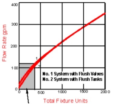
The fixture units approach is the most often used method for determining peak flow rates in industrial and commercial applications.
A fixture unit (FU) is a scale that has been arbitrarily established to allow all types of plumbing fittings to be stated in the same way. The fixture unit concept's main goal is to make it possible to compute the design load on a system made up of various types of fixtures, each with a different loading characteristic than the others. Fixture unit values are calculated using the possibility of many fixtures being used at the same time to determine the maximum allowable water supply and drainage load.
The fixture load for a business application must be determined according to most local plumbing codes. Figure can be used to determine the peak flow rate into the sewage lift station once the total fixture unit value has been computed. The fixture unit approach has been proved to be a conservative method of predicting the peak flow rate for a pumping station in the past.

Pump capacity should be equivalent to the peak flow rate of the drain line into the sewage lift station once that flow has been determined.
Material, force main sizing
The force main can be sized once the peak flow rate has been determined. The force main should have a minimum velocity of 2 feet per second (fps) and a maximum velocity of 5 fps. This will keep solids suspended without causing significant had loss.
To avoid clogging of the force main, the minimum pipe size should be 4 inches when wastewater pumps with at least a 2-1/2 inch solids passing capacity are used.
Force mains can be made of a variety of materials. In both underground and building force mains, PVC and polyethylene are becoming increasingly popular. Force mains should be constructed similarly to water lines, with thrust restrictions and blocks installed at bends and tees. To prevent air locking and syphoning, air release valves should be installed at high places.As needed, vacuum valves will be provided. Clean outs should also be considered so that areas where clogs are likely to form, such as low spots, may be cleared.
Analysis of the system head curve
The system head curve may be determined once the force main has been sized.
To calculate a total equivalent pipe length, include all elbows, pipe fittings, and pipe run lengths. The static head and the friction head are the two components of the system head curve. The vertical elevation of the fluid that the pump must overcome is known as static head. For a baseline of the system head curve, it is considered to be a constant head once the station is put into service. Its definition is as follows:
Static Head = System's lowest point minus the system's highest elevation opened to the atmosphere.
This is usually where the pipe exits. Elevation of all pumps off (Suggestions: Use the average elevation of "lead pump on" and "all pumps off"). This will provide you the pump's operating range's midpoint.)
Because the static head fluctuates during the pumping cycle, it will vary during the wet well pump down.The Hazen-Williams equation can be used to calculate principal friction losses. The system head curve can be calculated using the force main size, material, and equivalent length.The friction head in a particular system varies with the flow rate, as defined by the equation:

Where,
HL= Total friction head loss, feet of water
L=Length of equivalent pipe length of diameter ft.
C = Hazen-Williams flow coefficient,
Q= Flow rate, gallons per minute (gpm)
d = Internal pipe diameter, inches (in)
The head loss through the system should be calculated independently for each section based on pipe material, pipe diameter, and flow rate. When numerous pumps of the same size are used at the same time, the flow rate from the pump to the common force main is considered to be one divided by the number of pumps in use.
From 50% to 150 percent of the design flow, a general rule of thumb is to generate the system head curve with around 10 points. To determine the overall capacity of a multiple-pump station, a separate system head curve is usually necessary. The head curve of the system can then be plotted against the pump curve to establish the pump's operating point.
Netsol Water is Greater Noida-based leading water & wastewater treatment plant manufacturer. We are industry's most demanding company based on client review and work quality. We are known as best commercial RO plant manufacturers, industrial RO plant manufacturer, sewage treatment plant manufacturer, Water Softener Plant Manufacturers and effluent treatment plant manufacturers. Apart from this 24x7 customer support is our USP. Call on +91-9650608473, or write us at enquiry@netsolwater.com for any support, inquiry or product-purchase related query.


