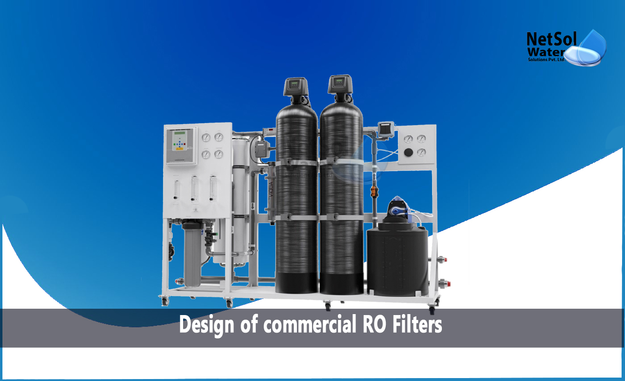
How to design of commercial RO Filters?
Commercial RO Plants are now used in a variety of applications, from small under-the-sink drinking water systems to massive municipal drinking water systems, due to their ability to remove both dissolved ionic and organic contaminants. The system design of Reverse Osmosis systems must be investigated to maximize performance and membrane life.
Design of commercial RO Filters
1. Feedwater sources:
The first consideration when building a RO system is the feedwater source. Water sources for brackish water reverse osmosis (BWRO) membranes can include industrial or municipal wastewater as well as surface or well water. Even if the source has undergone municipal treatment, it is crucial to look at where the municipality gets its water from. As the characteristics of the water source will have an impact on the RO membrane operation, this enables the design of the system in the best possible way.
The water source is one important consideration deciding the potential for fouling and scaling. The buildup of solids on the feed spacer or membrane surface is referred to as fouling. Dissolved solids from the feedwater are precipitated out on the concentrate side of the membrane during scaling, a chemical reaction.
Surface water may be derived from reservoirs, rivers, lakes, etc. Due to seasonal variations in suspended particles, biological pollutants, and total organic carbon (TOC), surface water is inherently vulnerable to fouling. It typically has low levels of hardness, heavy metals, and total dissolved solids (TDS). To destroy bacteria, surface water is typically disinfected, which increases the potential for organic fouling. The amount of suspended solids may rise during rain.
Turbidity and silt density index (SDI) are the two most accurate ways to measure suspended particles. Nephelometric turbidity units (NTUs), which are the most often used units for measuring turbidity, are increased as water transparency (or the water's capacity to scatter light) diminishes. According to test standard ASTM D-4189, SDI is a calculation of fouling potential. It is estimated by passing water through a 0.45-micron filter at 30 psi in a 500 ml jar both before and after the filter's typical 15-minute run period. By comparing the amount of time needed to fill a 500 ml jar with the RO feedwater before and after the test (ti and tf), it is possible to determine the percentage of plugging.
For best results, turbidity should be no higher than 1.0 NTU and no lower than 0.5 NTU. The RO inlet has acceptable SDI levels of less than 5.0 (15-minute test), however for best performance, SDI should be less than 3.0.
Groundwater, commonly referred to as well water, is obtained from subsurface resources. As a result of the earth's role as a natural filter when water sinks underground, it typically contains relatively little suspended particles. Well water frequently has significant levels of hardness, heavy metals, and potentially silica. It also typically has more dissolved solids.
2. Select Membrane and Membrane Type:
The design of a membrane system is most significantly affected by the feedwater's propensity to foul. Numerous substances found in the feedwater and concentrated at the membrane surface, such as dissolved organics, bacteria, particles, and other colloidal debris, can lead to membrane fouling.
A substitute measurement of the fouling material can be made using the silt density index value of the pretreated feedwater.
3. Selection of design flux:
Reverse osmosis systems are designed with a focus on a certain permeate flow rate and recovery rate. Recovery rate is the percentage of feed water that is converted to permeate processed water.
The tendency of the feedwater to scale and foul is the aspect that has the biggest impact on the design of the membrane system.
To reduce the rate of fouling and to assist prevent mechanical damage, a membrane system should be built so that each component runs within a range of advised operating conditions. These element operating circumstances are constrained by:
• maximum recovery
• maximum permeate flowrate
• minimum concentrate flowrate
• maximum feed flowrate
4. Calculation of module number:
In order to compute the module number, we need to know:
· Permeate flow (Qp) (m3/day)
· Membrane active area, (Ae) (m2)
· Design flux, (f) (L/m2.h)
Permeate flow measures the amount of water the machine can handle daily. You can obtain the membrane active area from the supplier of RO membranes.
5. Calculation of Pressure Vessel number (Nv):
For optimal concentrate flow, RO pressure vessels should typically have no more than six membranes per vessel.
Total number of pressure vessels required = (total number of modules) / (number of modules in a pressure vessel).
6. Balance the Permeate Flow Rate:
The final module of a system often has a lower permeate flow rate than the initial parts. Therefore, the pressure decrease in the feed channel and the rise in osmotic pressure from the feed to the concentrate are to blame for this.
The initial element's to last element's permeate flow rate ratio might rise dramatically in certain circumstances. These circumstances include:
· The high system recovery
· High feed salinity
· Low-pressure membranes
· High water temperature
· New membranes
Conclusion:
Reverse osmosis is, in general, a dependable and user-friendly technique. The feed water supply and user-specific needs, such as permeate quality and maintenance capabilities, can be taken into account to provide the highest level of reliability. While some systems are offered with the lowest capital cost, a high-quality system developed by skilled and experienced engineers can accomplish less maintenance, longer membrane life, and reduced cleaning frequency.
Do you need an advice or assistance on selecting the best water and waste water treatment unit? We have solutions for all your problems!
Let us now your problem, our experts will make sure that it goes away.
For an assistance or related query,
Call on +91-965-060-8473
Or write us at enquiry@netsolwater.com


