

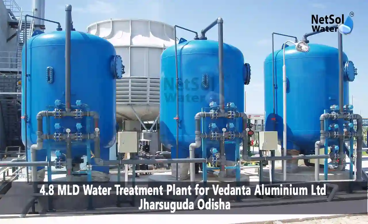
Case Study: 4.8 MLD Water Treatment Plant for Vedanta Aluminium Ltd Jharsuguda Odisha
Netsol Water designed, supplied, and commissioned a 4.8 MLD (Million Litres per Day) Water Treatment Plant (WTP) for Vedanta Aluminium Ltd. at its integrated aluminium smelting and manufacturing complex located in Jharsuguda, Odisha. The plant draws raw surface water from a dam situated in close proximity to the manufacturing facility and subjects it to a comprehensive multi-stage treatment process to produce potable water meeting the Bureau of Indian Standards (BIS IS:10500) drinking water specifications.
The treated water is distributed to the residential colony of the Vedanta Aluminium plant, serving the complete domestic water requirements of the resident workforce and their families - encompassing drinking water, bathing, cooking, sanitation, and general utility purposes. The hallmark achievement of this installation is the consistent maintenance of treated water turbidity at or below 1 NTU (Nephelometric Turbidity Units), far exceeding the BIS permissible limit of 5 NTU for drinking water.
This case study documents the project background, the detailed treatment process flow, design parameters of each treatment unit, performance data, and operational outcomes.
Project Background & Client Profile
About Vedanta Aluminium Ltd.
Vedanta Aluminium Ltd. is one of India's largest aluminium producers, operating a world-class integrated aluminium complex at Jharsuguda in the Jharsuguda district of Odisha. The complex includes an aluminium smelter, a captive thermal power plant, and supporting infrastructure spread over a vast industrial campus. The site houses thousands of employees and their families in an on-site residential colony, necessitating a reliable and safe supply of treated potable water for domestic use.
Problem Statement & Need for WTP
The primary source of water available in the vicinity of the plant is a dam located adjacent to the manufacturing complex. Dam water, being surface water, is subject to seasonal fluctuations in quality - particularly turbidity, suspended solids, biological contamination, and chemical parameters. Raw dam water typically exhibits:
• High turbidity during monsoon seasons, often exceeding 200–500 NTU
• Suspended solids including silt, clay, and algae
• Presence of coliform bacteria and other microbial contaminants
• Variable pH and dissolved minerals
• Organic matter leading to potential disinfection by-product formation
To supply safe, potable drinking water meeting BIS IS:10500 norms to the residential colony, Vedanta Aluminium commissioned Netsol Water Solutions to design and install a purpose-built 4.8 MLD WTP.
Project Objectives
• Design and commission a 4.8 MLD WTP to treat dam water to potable standards
• Achieve treated water turbidity consistently at or below 1 NTU
• Meet BIS IS:10500 standards for all drinking water parameters
• Ensure reliable, 24x7 operation with minimal chemical consumption
• Provide treated water for the complete domestic requirements of the residential colony
Design Basis & Raw Water Characteristics
Raw Water Source
The raw water source is a dam located in close proximity to the Vedanta Aluminium manufacturing plant. Dam water from this source is a surface water body fed by seasonal rainfall and catchment runoff. The dam serves as a reliable year-round source of raw water for the WTP intake.
Raw Water Quality Parameters
| Parameter | Normal Range | Peak / Monsoon | Unit |
|---|---|---|---|
| Turbidity | 20 – 80 | 200 – 500 | NTU |
| Total Suspended Solids (TSS) | 15 – 60 | 150 – 400 | mg/L |
| pH | 6.8 – 7.5 | 6.5 – 8.0 | — |
| Total Dissolved Solids (TDS) | 150 – 400 | 200 – 500 | mg/L |
| Total Coliform | 50 – 200 | 500 – 2000 | MPN/100 mL |
| Total Alkalinity | 80 – 200 | 100 – 250 | mg/L as CaCO3 |
| Total Hardness | 100 – 250 | 120 – 300 | mg/L as CaCO3 |
| Chloride | 30 – 80 | 40 – 100 | mg/L |
| Iron (Total) | 0.2 – 1.0 | 0.5 – 2.5 | mg/L |
Plant Design Capacity
| Design Parameter | Value |
|---|---|
| Installed Capacity | 4.8 MLD (200 m³/hr) |
| Operating Hours per Day | 24 Hours |
| Hydraulic Retention Time (Total) | Approx. 4–5 Hours |
| Design Population Served | Residential Colony — Vedanta Aluminium |
| Per Capita Demand Considered | 135 – 150 LPCD |
| Target Treated Water Turbidity | ≤ 1 NTU |
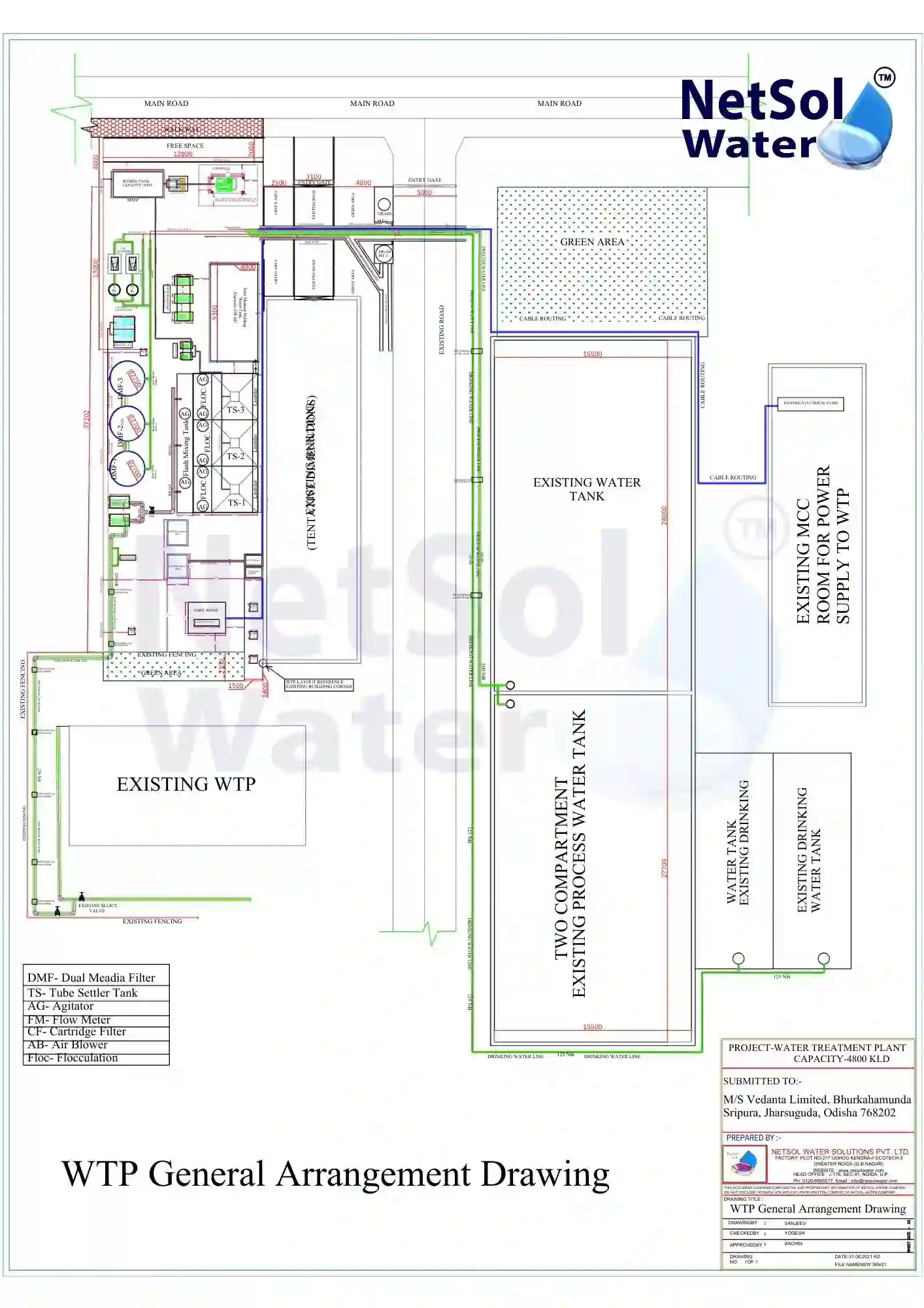
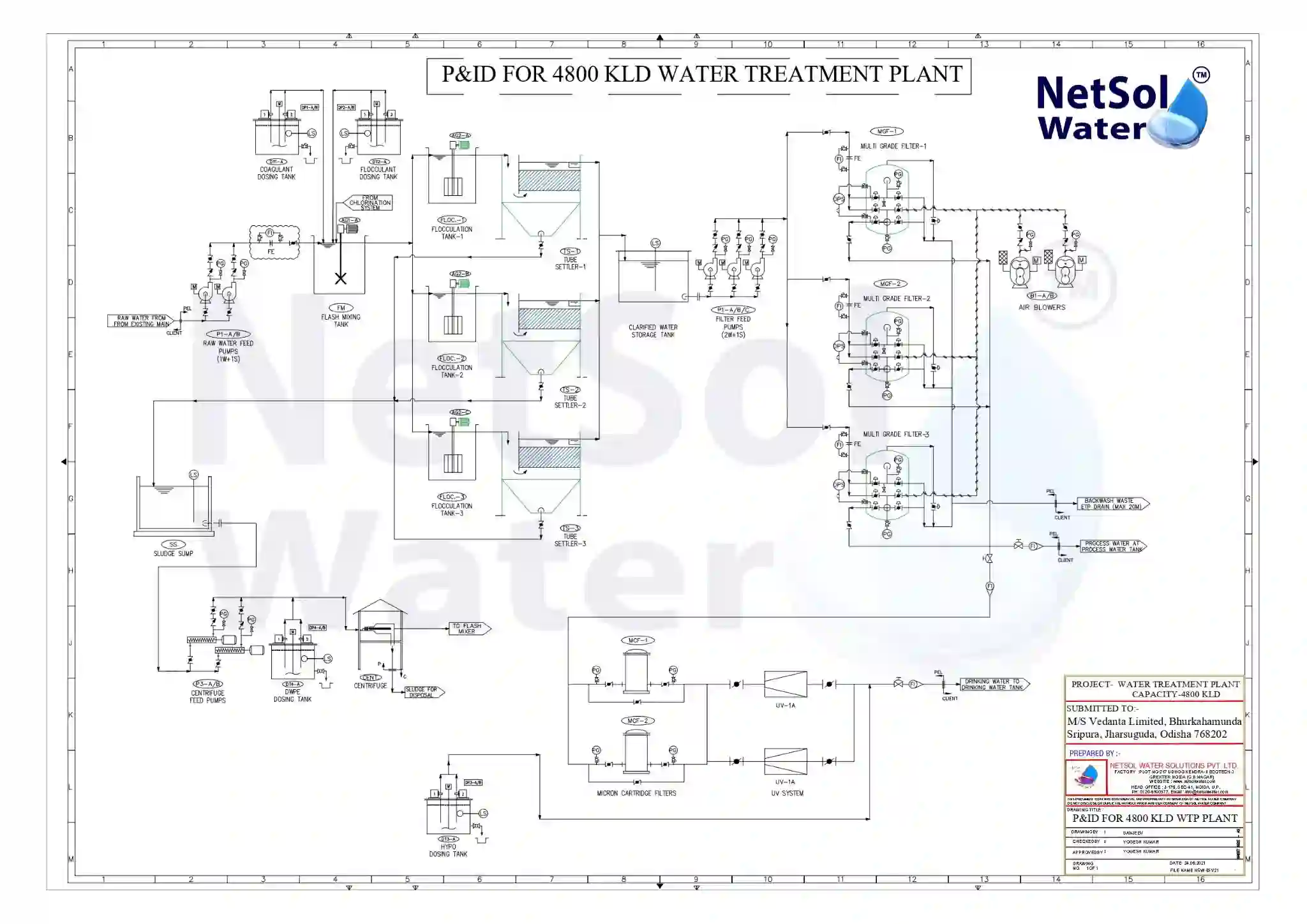
Detailed Process Flow Diagram, Description & GA Drawing
The WTP employs a conventional surface water treatment train consisting of eight sequential unit processes. Each stage is engineered to address specific contaminants and to reduce the load on subsequent units. The complete process flow is presented below with detailed technical parameters for each stage.
PROCESS FLOW DIAGRAM - 4.8 MLD WTP, VEDANTA ALUMINIUM LTD.
Sump / storage tank receiving dam water via gravity or pumping. Provides buffer storage and flow equalization.
HRT: ~2.5 hrs
Pump: Submersible / Centrifugal
Flow: 200 m³/hr
Inlet Screen: SS Bar Screen
Rapid mixing of coagulant (Alum / PAC) with raw water. Destabilizes colloidal particles by charge neutralization.
Dose: 10–30 mg/L
Mixing: Flash Mixer
Retention: 1–2 min
pH Range: 6.5–7.5
Gentle slow mixing allows micro-flocs to aggregate into large settleable flocs.
Mixing: Slow Mechanical Agitator
Velocity Gradient: 30–60 s?¹
HRT: 20–30 min
High-rate sedimentation using inclined PVC tubes increases effective settling area.
Tube Angle: 60°
Surface Loading Rate: 1–2 m³/m²/hr
Sludge Removal: Hopper Bottom
Primary disinfection using sodium hypochlorite ensures pathogen inactivation.
Dose: 2–5 mg/L
Contact Time: 20–30 min
Residual Chlorine: 0.5 mg/L
Removes chlorine taste, odor, color, dissolved organics and improves water clarity.
Bed Depth: 900–1200 mm
Filtration Rate: 8–10 m³/m²/hr
Backwash: Periodic
Depth filtration through layers of graded media removes residual suspended solids, turbidity, and fine particles to achieve clear water.
Filtration Rate: 8–10 m³/m²/hr
Bed Depth: ~1 m
Backwash Frequency: Every 24–48 hrs
Outlet Turbidity Target: ≤ 1 NTU
Final storage of treated potable water. Post-chlorination ensures residual disinfectant before supply to the residential colony via distribution pumps.
Post Chlorination Dose: 0.5–1.0 mg/L NaOCl
Free Residual Chlorine at Plant Outlet: ≥ 0.2 mg/L
Distribution: Pumping to Overhead Tanks
Supply: Drinking Water Supply — 24 hrs
Chemical Dosing System
Precise chemical dosing is critical to effective water treatment. The WTP employs a fully instrumented chemical dosing system with dosing pumps, solution preparation tanks, and flow-proportional control.
| Chemical | Point of Addition | Purpose | Typical Dose | Control |
|---|---|---|---|---|
| Poly Aluminium Chloride (PAC) | Coagulation Tank Inlet | Coagulation / Charge Neutralisation | 10–30 mg/L | Flow Proportional |
| Anionic Polyelectrolyte | Flocculation Tank | Floc Strengthening & Size Enhancement | 0.1–0.5 mg/L | Flow Proportional |
| Sodium Hypochlorite (NaOCl) | Chlorine Contact Tank | Primary Disinfection — Bacteria & Viruses | 2–5 mg/L | ORP / Cl? Analyser |
| Sodium Hypochlorite (NaOCl) | Treated Water Tank | Post-Chlorination — Distribution Residual | 0.5–1.0 mg/L | Flow Proportional |
| Alum (Aluminium Sulphate) — Backup | Coagulation Tank | Alternative Coagulant (Seasonal) | 20–40 mg/L | Manual / Timer |
| Lime / Soda Ash | Coagulation Stage | pH Correction (if required) | As Required | pH Analyser |
Plant Performance & Treated Water Quality
The WTP consistently achieves treated water quality well within the Bureau of Indian Standards IS:10500 drinking water norms. The table below compares raw water quality, treated water quality achieved, and the BIS IS:10500 permissible limits.
| Parameter | Unit | Raw Water (Typical) | Treated Water (Achieved) | BIS IS:10500 Limit |
|---|---|---|---|---|
| Turbidity | NTU | 20 – 500 | ≤ 1.0 | 1 (5 Max.) |
| pH | — | 6.8 – 7.5 | 7.0 – 7.5 | 6.5 – 8.5 |
| Total Dissolved Solids | mg/L | 150 – 400 | < 200 | 500 (2000 Max.) |
| Total Hardness | mg/L CaCO? | 100 – 250 | < 200 | 200 (600 Max.) |
| Total Coliform | MPN/100 mL | 50 – 2000 | Nil | Nil |
| E. Coli | MPN/100 mL | Present | Absent | Absent |
| Free Residual Chlorine | mg/L | Nil | 0.5 – 1.0 | 0.2 Min. |
| Iron (Total) | mg/L | 0.2 – 2.5 | < 0.1 | 0.3 Max. |
| Taste & Odour | — | Earthy / Musty | Unobjectionable | Unobjectionable |
| Colour | Hazen Units | 15 – 50 | < 5 | 5 (15 Max.) |
Instrumentation, Monitoring & Control
The WTP is equipped with online monitoring instruments and control systems to enable automated, reliable operation and real-time quality assurance.
| Instrument | Location | Purpose |
|---|---|---|
| Online Turbidimeter | Inlet + Outlet (MGF) | Continuous turbidity monitoring; alarm if outlet > 1 NTU |
| pH Analyser / Controller | Coagulation Tank & Treated Water Tank | Maintains optimal pH for coagulation and disinfection |
| Chlorine Analyser (DPD / Amperometric) | CCT Outlet & Distribution Header | Monitors free and total chlorine residuals continuously |
| Electromagnetic Flow Meter | Inlet & Outlet Main Lines | Measures and records total flow; enables proportional chemical dosing |
| Level Transmitter / Float Switch | All Tanks | High/low level alarms; automatic pump control |
| Differential Pressure Gauge | ACF & MGF | Indicates filter loading; triggers backwash when ΔP exceeds set point |
| ORP Meter | Chlorine Contact Tank | Oxidation-Reduction Potential for disinfection efficacy confirmation |
| SCADA / PLC Panel | Central Control Room | Centralised monitoring, alarming, data logging, and remote control |
Sludge Management
Water treatment generates sludge primarily from the tube settler and filter backwash operations. Proper sludge management is essential for environmental compliance and plant efficiency.
• Tube Settler Sludge: Collected via bottom hoppers and directed to a sludge thickener / sludge drying bed (SDB)
• Filter Backwash Water: Backwash water from ACF and MGF is collected in a backwash recovery tank and recycled to the raw water collection tank (recovery of ~5% total flow)
• Sludge Drying Beds (SDB): Solar-assisted drying of settled sludge; dried sludge cake disposed as per applicable environmental norms
• Sludge Volume: Approximately 1–3% of total plant throughput (dependent on raw water turbidity)
• Environmental Compliance: All sludge handling in compliance with CPCB and OSPCB guidelines
Key Project Achievements
| Achievement | Details |
|---|---|
| Turbidity Control | Consistently ≤ 1 NTU — far exceeding BIS IS:10500 standard of 5 NTU |
| Zero Pathogen Record | Nil total coliform and E. Coli in all treated water samples |
| Full BIS IS:10500 Compliance | All parameters within permissible limits for drinking water |
| Reliable 24×7 Supply | Continuous potable water supply to residential colony without interruption |
| Seasonal Adaptability | Effective treatment during peak monsoon turbidity (>500 NTU raw water input) |
| Backwash Water Recovery | ~5% recovery of backwash water, minimizing raw water wastage |
| Taste & Odour Elimination | ACF ensures no earthy taste, musty odour, or chlorine smell in supply water |
Operation & Maintenance Guidelines
1. Routine Daily Operations
• Monitor inlet and outlet turbidity every 2 hours; log readings
• Check and adjust chemical dosing rates proportional to raw water flow and turbidity
• Verify free residual chlorine at CCT outlet and distribution header - maintain 0.5–1.0 mg/L at plant, ≥ 0.2 mg/L at farthest point of use
• Inspect all chemical dosing pumps, level sensors, and flow meters for correct functioning
• Log all instrument readings in the plant O&M register
2. Filter Backwash Protocol
• Initiate backwash when differential pressure across ACF or MGF exceeds 0.3–0.5 bar, or on a time-based schedule (every 24–48 hours)
• Backwash sequence: Air scouring (3–5 min) → Combined air + water (3 min) → Water wash alone (5–8 min)
• Backwash water collected in recovery tank and recycled to inlet
• Log backwash duration, volume, and post-backwash turbidity
3. Periodic Maintenance
• Monthly: Calibrate pH, turbidity, and chlorine analysers against certified standards
• Quarterly: Inspect and clean tube settler modules; remove accumulated sludge
• Six-Monthly: Inspect ACF carbon bed for exhaustion (iodine number test); plan replacement if required
• Annual: Complete overhaul of all dosing pumps, mechanical flocculators, and distribution pumps; replace seals, impellers as needed
Watch the Water Treatment Plant Project Video
This video provides an overview of the engineering design, operational reliability, and water quality performance achieved by Netsol Water Solutions through this large-scale industrial water treatment project.
Conclusion
Netsol Water Solutions Pvt. Ltd. has successfully designed, installed, and commissioned a 4.8 MLD Water Treatment Plant for Vedanta Aluminium Ltd. at Jharsuguda, Odisha. The plant transforms raw dam water - subject to wide seasonal quality variations including high turbidity, biological contamination, and suspended solids - into safe, high-quality potable water meeting and surpassing the Bureau of Indian Standards IS:10500 norms.
The eight-stage treatment process - from raw water collection through coagulation, flocculation, tube settler clarification, chlorine disinfection, activated carbon filtration, multi-grade filtration, to final treated water storage - represents a technically robust and proven engineering solution for surface water treatment. The hallmark achievement of maintaining treated water turbidity at or below 1 NTU demonstrates the high precision engineering and meticulous operational protocols employed.
The WTP provides Vedanta Aluminium Ltd.'s residential colony with a completely reliable supply of safe drinking water for all domestic needs - safeguarding the health and wellbeing of the workforce and their families residing at the site. This project stands as a testimony to Netsol Water Solutions' expertise in industrial and community water treatment across India.