
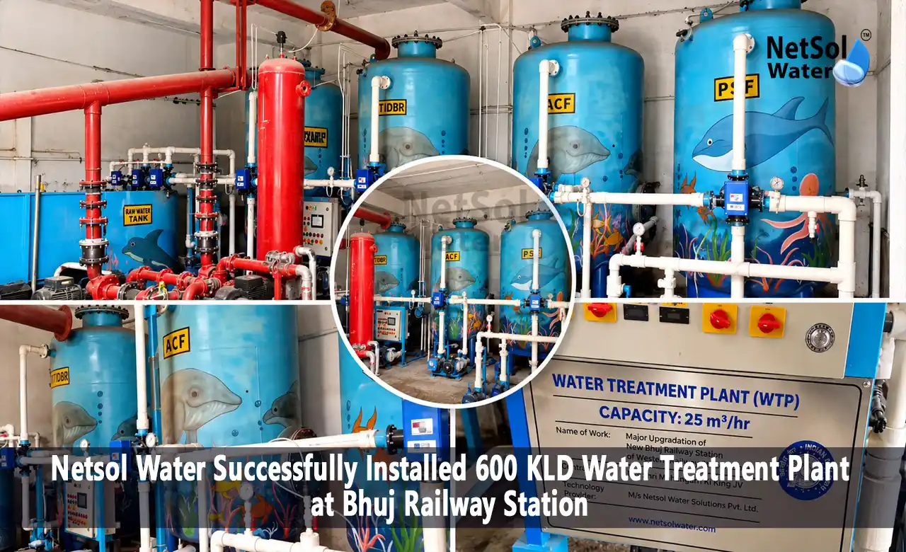
Case Study: Installed 600 KLD Water Treatment Plant at Bhuj Railway Station
Netsol Water completed a water treatment plant at Bhuj Railway Station in Gujarat in 2026. The project has two WTP systems fed by a borewell. One is rated at 25 m³/hr and the other at 5 m³/hr, so the nominal combined flow is 30 m³/hr. Run for 20 hours a day, that gives 600 m³/day, or 600 KLD. The scope document lists the intended use of the treated water as drinking and other purposes.
This case study uses the two P&ID drawings, the scope document and our site video. It covers the system configuration, the capacity calculation, the listed water quality parameters and the engineering principles behind a plant of this type.
Project Overview
| Item | Detail |
|---|---|
| Project | Installed 600 KLD Water Treatment Plant at Bhuj Railway Station |
| Location | Bhuj, Gujarat, India |
| Completed | 2026 |
| Raw Water Source | Borewell |
| First WTP System | 25 m³/hr (Nominal) |
| Second WTP System | 5 m³/hr (Nominal) |
| Combined Flow | 30 m³/hr (Nominal) |
| Operating Basis | 20 hours per day |
| Calculated Daily Throughput | 600 m³/day = 600 KLD |
| Stated Use of Treated Water | Drinking and other purposes |
The 600 KLD figure is calculated from the nominal flow rates and the 20-hour daily operating schedule.
Project Background and Requirements
A railway station uses water in many places at once. Passengers drink it and wash their hands. Toilets, platform cleaning and pantry areas draw on the same supply. Demand also swings with train timings, so the plant has to be sized for peaks and not just averages.
Borewell water adds its own questions. Groundwater can carry hardness, turbidity, iron or dissolved salts, and quality can shift between seasons or as a well ages. That is why a treatment plant is normally designed around a stated set of water quality parameters instead of a flow rate alone.
A plant like this starts from a defined scope: the water source, the quantity, the operating hours, the intended use and the quality parameters. Each one shapes the design. Source and quality decide the treatment stages, quantity and operating hours decide equipment size, and intended use decides how closely the treated water must be tested. Netsol Water follows the same approach when it designs water treatment plants for different industries and institutions.
Project Objectives
The scope points to four objectives.
1. Design capacity. Provide 25 m³/hr and 5 m³/hr systems that together support 30 m³/hr for 20 hours a day.
2. Intended use. Supply treated water for drinking and other purposes. The scope document labels this entry "mode of disposal". It describes where the treated water goes, which is to people and station uses, and it should not be read as wastewater disposal.
3. Quality targets. Work toward the outlet hardness and turbidity targets listed in the scope, covered below.
4. Verification. Confirm actual performance through laboratory testing, and drinking use needs more than two parameters checked.
Water Treatment Plant Design and System Configuration
The plant is built as two separate WTP systems, each documented in its own P&ID.
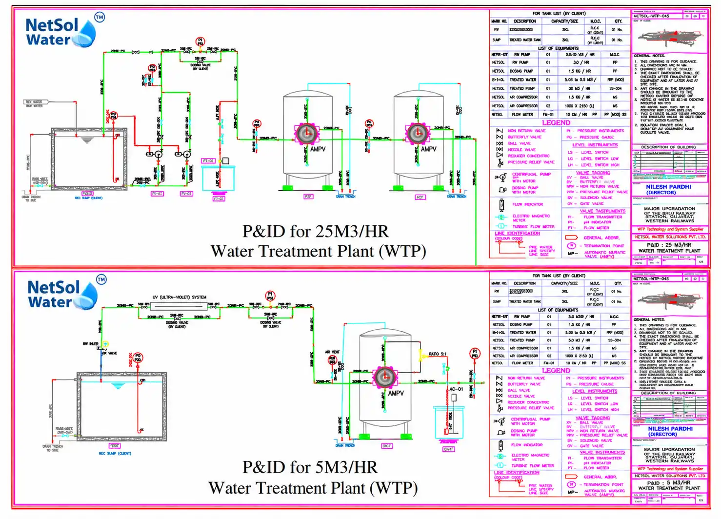
Figure shows the P&ID for the 25 m³/hr system and 5 m³/hr system. Each drawing records the equipment, piping, valves, instruments and tanks of its system, which makes the P&ID the main design reference for both operation and maintenance.
The nominal flows add up directly. 25 m³/hr plus 5 m³/hr gives 30 m³/hr. The larger system carries about five-sixths of the combined flow and the smaller one the remaining sixth.
A split layout has practical advantages. Operators can run one unit while the other is isolated for service, and the smaller unit can handle a separate or lower demand without running the larger one at part load.
Water Treatment Process Flow
A P&ID is a process drawing, not a photograph or a layout plan. It shows how water moves through the system: tanks, pumps, vessels, interconnecting pipes, valves and instruments, joined by flow arrows. To read it, start at the raw water inlet, follow the arrows, and note what each symbol does along the way.
In a typical borewell-fed WTP, the treatment stages are chosen to match the raw water quality and the outlet targets. Common stages include raw water storage, filtration to reduce turbidity and suspended solids, iron removal where iron is present, softening to reduce hardness, and a treated water tank from which water is distributed. Disinfection or membrane stages are added when the quality requirements call for them. The two P&IDs show the exact arrangement of each system at Bhuj Railway Station.
Each of these stages does a specific job. Filtration passes water through granular media that traps suspended particles, which lowers turbidity. Iron removal oxidises dissolved iron so it can be filtered out, which protects pipes and downstream equipment from staining and fouling. Softening uses ion exchange resin that swaps calcium and magnesium for sodium, which lowers hardness and prevents scale. Storage tanks sit between stages so that pumps and filters can run at steady rates even when demand rises and falls.
The outlet targets of hardness below 50 mg/L and turbidity below 1 NTU show what the treatment has to achieve. With raw water hardness listed up to 450 mg/L, the plant needs a stage that brings hardness down substantially, and a stage that brings turbidity from a listed limit of 50 NTU to below 1 NTU.
Whatever stages a plant uses, a P&ID is built from the same basic elements:
1. Tanks hold raw or treated water and smooth out the difference between supply and demand.
2. Pumps move water between stages and to the point of use.
3. Valves isolate equipment, direct flow or allow drain and bypass operations.
4. Instruments such as flow meters, pressure gauges and level devices let operators see how the system is behaving.
Reading the two drawings side by side shows how each system is arranged from the raw water inlet to the treated water outlet.
Installation and Commissioning
The Bhuj Railway Station WTP was completed in 2026, and Netsol Water published a site tour video of the installation in June 2026.
In general, installing a plant of this type means placing the equipment as per the layout, connecting the piping against the P&ID, installing instruments, completing electrical connections and then checking the system before it goes into service. Typical commissioning checks include leak testing the pipework, confirming pump rotation, testing valve operation, flushing the lines and running the system while observing flow and pressure.
After that comes water quality verification. Samples taken from the treated water should be tested by a laboratory, and the results kept as the project record. Together, these steps take a plant from installed equipment to a system ready for regular service.
Capacity Calculation and Operation
The capacity is built up in three steps.
1. Combined nominal flow rate: 25 + 5 = 30 m³/hr
2. Daily throughput at 20 operating hours: 30 × 20 = 600 m³/day
3. Convert to litres, since 1 m³ = 1,000 litres: 600 m³/day = 600,000 litres/day = 600 KLD
This is a calculated daily throughput based on the supplied nominal flow rates and the stated 20-hour schedule. It is not independently measured production. Actual output depends on how many hours the plant runs, the feed water available, the condition of the equipment and the demand on a given day. Operating records, such as flow meter readings and run-hour logs, are what establish real daily production.
A 20-hour schedule leaves about four hours a day without operation. Plants are often scheduled this way to allow time for cleaning, routine checks and maintenance.
Raw Water Quality Parameters
The scope document lists these inlet limits for the borewell water.
| Parameter | Limit Listed in the Supplied Document |
|---|---|
| Turbidity | Less than 50 NTU |
| Temperature | 4–38°C |
| pH | 7–7.5 |
| Hardness | Less than 450 mg/L |
| Free Chlorine | Less than 1 mg/L |
| Iron (Fe) | Less than 0.1 mg/L |
| SDI | Less than 2.5 |
| Hydrogen Sulphide | Not allowed |
| Organics | Less than 1 mg/L |
These are the design limits for the inlet water. Actual borewell water quality is confirmed by laboratory analysis.
The temperature range of 4–38°C is roughly 40–100°F.
A few of these matter more than they look. Turbidity shows how much suspended material the water carries, which affects how hard the treatment stages have to work. Hardness reflects dissolved calcium and magnesium, which cause scale in pipes and fittings. Iron can stain fixtures and foul filter media, which is why its limit is tight. SDI, the silt density index, is a measure of fouling tendency that matters for any membrane-based stage. A low SDI limit helps protect downstream equipment from fouling.
Borewell water is often clear when it is drawn, which can hide dissolved hardness and iron. Water that looks clean can still scale pipes or stain fixtures, so the quality parameters matter even when the water looks acceptable. Groundwater can also change over time, so periodic testing of the raw water helps keep the treatment design matched to the source.
Treated Water Quality and Intended Use
The scope lists two outlet targets.
| Parameter | Unit | Target Shown in Document |
|---|---|---|
| Hardness | mg/L | Less than 50 |
| Turbidity | NTU | Less than 1 |
The scope document lists these as CPCB norms. Actual performance is confirmed through laboratory testing of the treated water.
Actual treated water quality is established by laboratory testing, not by the target. For drinking use, a complete assessment covers physical, chemical and microbiological parameters against the applicable drinking-water standard. Hardness and turbidity alone do not show that water is potable. A laboratory test against the applicable drinking-water standard confirms whether treated water is suitable for drinking.
In India, drinking water is checked against IS 10500, the Bureau of Indian Standards specification for drinking water. A full test normally covers physical parameters such as colour, odour and turbidity, chemical parameters such as pH, total dissolved solids, hardness, chlorides, sulphates, nitrates, fluoride and iron, and microbiological parameters such as total coliform and E. coli. Sampling at the treated water outlet and at taps further down the distribution line shows whether quality holds all the way to the point of use.
Installation Challenges and Engineering Considerations
Installing a two-system plant at a working railway station involves several practical considerations.
1. Piping layout. Two systems need clear routing so that each can be isolated without disturbing the other.
2. Equipment access. Pumps, valves and instruments should be reachable for inspection, cleaning and replacement.
3. Space and operating environment. Platform and station buildings are busy, so equipment placement affects safety and day-to-day access.
4. Commissioning checks. Each system should be tested and flushed before it supplies water for use.
5. Maintenance access. Service points should stay open after installation, not boxed in by later works.
Project Benefits and Expected Outcomes
The documented benefits come from the design itself.
1. Planned treatment capacity. A nominal 30 m³/hr and a calculated 600 KLD give station operators a defined treated-water capacity to plan around.
2. Water supply management. Two systems give flexibility in how water is routed and, if the design allows, how units are serviced. The drawings show whether it does.
3. Monitoring. Instruments shown on the P&IDs let operators watch plant behaviour and spot problems early.
4. Defined quality targets. Listed inlet limits and outlet targets give a clear basis for testing and review.
With regular monitoring and maintenance, a plant of this kind can support a steady supply of treated water for station needs.
Operation and Maintenance
Good habits matter more than any single procedure. A plant like this benefits from:
. regular pump inspection for noise, leaks and vibration
. monitoring of filter pressure and flow, where filters exist
. periodic checks of instruments, with calibration as the manufacturer advises
. scheduled laboratory testing of treated water
. written maintenance and water quality records
Specific intervals and procedures follow the manufacturer's manuals and the final plant design, so a written maintenance schedule should be set with the project engineer.
Daily and weekly logs make trends visible. A slow rise in filter pressure, a drop in flow or a change in treated water turbidity usually shows up in the records before it becomes a breakdown. Keeping spares for common wear items, such as seals, gauges and pump consumables, reduces downtime. Netsol Water also offers customer support for plant operation and service.
Watch the Bhuj Railway Station Water Treatment Plant Installation
Our site tour video, published in June 2026, shows the Bhuj Railway Station WTP installation. It is a useful companion to the drawings, since it lets you see the plant on site alongside the P&IDs. It gives a visual overview of the installation and works well alongside the P&IDs and the data in this case study.
Conclusion
The Bhuj Railway Station project combines a 25 m³/hr and a 5 m³/hr WTP system for a nominal 30 m³/hr. At 20 operating hours a day, that is a calculated 600 m³/day, or 600 KLD. The raw water is from a borewell, and the stated use is drinking and other purposes.
The listed inlet limits and outlet targets are design information. Laboratory testing and operating records are what show real performance. For drinking use, water should be checked against the applicable drinking-water standard across all relevant parameters.
If you are planning a water treatment plant for a railway station, institution or industrial site, contact Netsol Water with your water source, flow requirement and intended use. Our team can review your requirements and discuss a suitable design. For a larger example, read how a dam water treatment plant at Vedanta, Odisha treats raw water in stages.
Frequently Asked Questions (FAQs)
Q1. What is the capacity of the Water Treatment Plant at Bhuj Railway Station?
It has a combined nominal flow of 30 m³/hr, which gives a calculated 600 KLD at 20 operating hours a day.
Q2. How is the 600 KLD daily throughput calculated?
25 + 5 = 30 m³/hr. 30 × 20 = 600 m³/day. 600 m³ equals 600,000 litres, so 600 KLD. This is calculated, not measured.
Q3. What is the raw water source for the project?
A borewell.
Q4. What are the flow rates of the two WTP systems?
25 m³/hr for the first system and 5 m³/hr for the second.
Q5. What treated water quality targets are listed in the project scope?
Hardness below 50 mg/L and turbidity below 1 NTU. The document labels them "CPCB Norms". They are targets, not measured results.
Q6. Can the treated water be used for drinking purposes?
The scope lists drinking and other purposes as the intended use. Water for drinking should be tested in a laboratory against the applicable drinking-water standard across physical, chemical and microbiological parameters.