

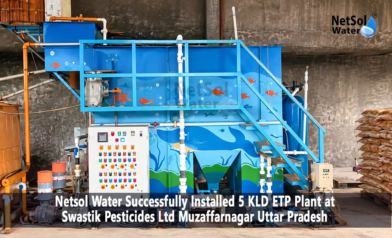
Case Study: Installed 5 KLD ETP Plant at Swastik Pesticides
In 2026, Netsol Water installed a 5 KLD ETP plant at Swastik Pesticides Ltd in Muzaffarnagar, Uttar Pradesh. It is a package-type effluent treatment plant built in MSFRP. The plant uses MBBR (Moving Bed Biofilm Reactor) technology to treat wastewater from pesticide manufacturing. Chemical treatment comes ahead of the biological stage, and a PLC control panel runs the plant.
Installation and commissioning took 6 days. The main challenge was limited space at the site.
This page explains what was installed, how each treatment stage works and how the space problem was handled.
| Detail | Confirmed Project Information |
|---|---|
| Client | Swastik Pesticides Ltd |
| Location | Muzaffarnagar, Uttar Pradesh, India |
| Installation Year | 2026 |
| Capacity | 5 KLD |
| Plant Type | Package-Type ETP |
| Construction Material | MSFRP |
| Technology | MBBR |
| Wastewater Source | Pesticide Manufacturing |
| Automation | PLC Control Panel |
| Chemical Treatment | Yes |
| Installation Time | 6 Days |
| Main Challenge | Space Constraint |
About the Project and Wastewater Treatment Requirements
Swastik Pesticides Ltd manufactures pesticides at its unit in Muzaffarnagar. Wastewater from a pesticide plant does not come from a single pipe. In general, it comes from process washing, equipment cleaning, floor washing and similar activities, and the mix changes with the products being made.
That changing mix is the real difficulty. Organic load, suspended solids and pH can shift from one batch to the next. A plant for this kind of wastewater needs to even out the flow, correct the pH, remove what chemical treatment can remove, and only then pass the water to the biological stage.
Why a 5 KLD Effluent Treatment Plant Was Required?
KLD means kilolitres per day, so 5 KLD is 5,000 litres of treatment capacity per day. That is small by industrial standards, but a small flow does not remove the obligation. Industrial units in India operate under consent conditions set by the State Pollution Control Board, and pesticide manufacturing wastewater needs proper treatment before any discharge or reuse.
If you are planning a similar unit, our effluent treatment plant manufacturer page explains the wider range of ETP systems we build.
Understanding Pesticide Manufacturing Wastewater Characteristics
No two pesticide plants discharge the same wastewater. A published review of pesticide production wastewater reports pH from 0.5 to 14, COD from 150 to 33,750 mg/L and BOD from 30 to 11,590 mg/L across different studies.
The table below gives reference values to help you read the numbers. It is not data from this project.
| Parameter | Discharge |
|---|---|
| BOD | 30 mg/L (CPCB general standard, inland surface water) |
| COD | 250 mg/L (CPCB general standard, inland surface water) |
| TSS | 100 mg/L (CPCB general standard, inland surface water) |
| pH | 6.0 to 9.0 (US EPA reference for pesticide chemicals manufacturing) |
These are illustrative reference values only. They are not laboratory results from Swastik Pesticides Ltd, and they are not the limits applicable to this unit, which come from its own consent conditions. Actual wastewater characteristics depend on the manufacturing process, the chemicals used and how often equipment and floors are cleaned.
1. Biological Oxygen Demand (BOD)
BOD, also called Biochemical Oxygen Demand, shows how much oxygen microorganisms need to break down the biodegradable organic matter in water. A high BOD means a heavy organic load for the biological stage.
2. Chemical Oxygen Demand (COD)
COD measures the oxygen needed to oxidise both biodegradable and non-biodegradable matter chemically. In pesticide wastewater it usually sits well above BOD, because many process chemicals resist biological breakdown. A wide gap between COD and BOD tells a designer that biology alone will not do the whole job, which is one reason chemical treatment comes before the MBBR stage.
3. Total Suspended Solids (TSS)
TSS is the amount of solid particles held in the water.
4. pH Level and Its Importance
pH tells you whether the water is acidic or alkaline. Microorganisms work in a narrow range, and large swings slow them down or kill them. Pesticide process water can swing far in either direction. One study from an agrochemical belt near Mumbai reports alkaline pH of 12 to 14 in pesticide wastewater. pH also decides how well chemical dosing works, which is why this plant has a dedicated pH correction stage.
MBBR-Based ETP Technology and Treatment Process
MBBR places small plastic carrier media in an aerated tank. Bacteria grow as a thin biofilm on the media, and the media keep moving through the water. This gives a large active surface area in a small tank volume, which helps on a tight site. Our blog on MBBR technology covers the basics.
The stages below follow the path of the water. The descriptions are general explanations of each stage, written for pesticide wastewater.
1. Collection Tank
Wastewater from the manufacturing unit reaches the collection tank first. It receives water from different points in the factory and passes it to the plant in a controlled way.
2. Equalisation Tank
Pesticide units often work in batches, so flow and strength vary through the day. The equalisation tank blends these differences into a steadier feed. This matters most for the biological stage, because bacteria cope with gradual change far better than with sudden shock loads.
3. pH Correction
Here the pH is adjusted to a range that suits the chemical and biological stages that follow. Acid or alkali is dosed according to what the incoming water needs.
4. Primary Treatment
The project includes chemical treatment, and primary treatment is where it is applied. In general, chemical dosing at this stage helps fine suspended matter come together and settle, and it takes out part of the organic load before biology begins.
5. Biological Treatment Using MBBR Technology
The pre-treated water now enters the MBBR tank. An air supply keeps the media moving and gives the bacteria the oxygen they need. They feed on the biodegradable organic matter and bring down BOD and part of the COD. Because the biofilm sticks to the media instead of floating free, an MBBR system generally handles load variation better than a suspended-growth system of similar size. Pesticide compounds can still inhibit bacteria, which is why the earlier stages exist.
6. Clarifier
Biological treatment releases loose biomass along with the water. The clarifier gives the water time to rest, so solids settle at the bottom while clearer water moves ahead. The settled sludge is drawn off and handled separately.
7. Filtration
Filtration polishes the clarified water by catching fine particles that did not settle. It improves clarity and protects whatever uses the water later.
8. Treated Water Tank
Treated water is stored in this tank. It is also the natural place to collect samples. Before any reuse, the stored water should be tested against what the intended use requires.
5 KLD Package ETP Plant Design and Construction Details
1. MSFRP Construction
MSFRP generally means mild steel with an FRP (fibre reinforced plastic) layer. The steel gives structural strength, and the FRP layer resists corrosion from chemical-bearing wastewater. In a package plant, tanks are built as ready units and brought to site, so the work left at the site is mostly placement and connection.
2. Chemical Dosing Arrangement
Chemical treatment is confirmed for this plant. A dosing arrangement adds treatment chemicals in controlled quantities where they are needed, mainly at pH correction and primary treatment. The right dose depends on the wastewater, so it is normally fixed by testing and then reviewed during operation. Chemical names and quantities are not published here.
3. PLC-Based Control Panel
PLC stands for programmable logic controller. The panel runs the plant’s electrical equipment according to set logic, so operators do not have to switch each item by hand. Typical tasks include start and stop sequences, timers and alarms.
ETP Plant Installation and Commissioning at Swastik Pesticides Ltd
The plant was installed at the Muzaffarnagar unit in 2026. Installation and commissioning together took 6 days.
1. Site Preparation and Equipment Placement
With a package plant, the main units arrive built. The job at site is to position them correctly, check that they sit in the order the water flows and keep them accessible. Because space was tight, the position of each unit had to be settled before work began.
2. Piping and Electrical Connections
Once the units are placed, piping joins them so water can move from one stage to the next, and the factory’s wastewater line is connected to the collection tank. Electrical work links the plant’s equipment to the PLC panel and the power supply.
3. Installation and Commissioning in 6 Days
Installation and commissioning were completed in 6 days. Commissioning means running the plant to confirm that each stage and control works as intended before handover.
Installation Challenges and Solutions
1. Managing Space Constraints at the Installation Site
Space was the main challenge. The answer was a compact package-type plant, supported by the way MBBR packs a large active surface into a small tank volume.
2. Equipment Arrangement and Installation Planning
Planning followed the process. Stages were arranged in the order the water moves through them, which keeps piping short and the flow easy to follow. Settling the layout before the units arrive is what makes a 6-day schedule realistic.
Treated Water Quality and Reuse Applications
Reuse is a possible benefit of this plant, not an automatic one. Whether treated water suits a given use depends on its tested quality, the needs of that use and the standards that apply. None of the uses below should start without testing.
1. Water Reuse for Gardening
Treated water may be considered for ornamental plants and green areas inside the premises. Pesticide wastewater calls for extra care, because residues and dissolved salts could affect plants and soil.
2. Water Reuse for Floor Washing and Flushing
Floor washing and flushing are lower-grade uses, so they are the usual first candidates for reuse. The water should be free of strong odour and visible solids, and staff contact with it should be considered. Here too, testing decides.
3. Potential Process Water Reuse
Process reuse is the strictest case. It depends on the process, the product and the quality the process needs. Any contamination risk to the product must be ruled out. Many processes will need extra polishing before reuse, such as the treatment described on our page about industrial RO plants and water recycling.
Project Outcomes and Practical Benefits
The reported benefits are practical ones. We have no measured savings or efficiency figures to publish, and none are claimed here.
1. Better wastewater treatment comes from the staged design. Each step prepares the water for the next, so the biological stage works on pre-treated water.
2. Water reuse opportunities open up once the treated water is tested.
3. Easier plant operation comes from the PLC control panel and the package layout. Operators work with one panel and a compact plant, not a scattered system.
4. Reduced wastewater discharge follows from reuse. Water that is tested and reused inside the premises does not have to leave it.
For the regulatory side of organic chemical wastewater, see our note on CPCB guidelines for ETP plants in organic chemical manufacturing.
5 KLD ETP Plant Installation Video at Swastik Pesticides Ltd
The video below gives a visual overview of the ETP plant installation at Swastik Pesticides Ltd. It is the original installation video for this project.
Frequently Asked Questions (FAQs)
Q1. What is the capacity of the ETP plant installed at Swastik Pesticides Ltd?
The plant has a capacity of 5 KLD, which is 5,000 litres per day. It is a package-type effluent treatment plant built in MSFRP.
Q2. Which technology is used in this ETP plant?
The plant uses MBBR (Moving Bed Biofilm Reactor) technology for biological treatment. Chemical treatment is applied before the biological stage, and a PLC control panel operates the plant.
Q3. Why is MBBR technology used in industrial ETP plants?
MBBR grows bacteria as a biofilm on moving media, which gives a large treatment surface in a small tank. It generally copes well with changing loads and does not need the sludge return that conventional activated sludge systems need. These points make it a fit for compact industrial sites.
Q4. How many days did the installation take?
Installation and commissioning of the plant at Swastik Pesticides Ltd were completed in 6 days.
Q5. What is MSFRP construction in an ETP plant?
MSFRP generally means mild steel with an FRP (fibre reinforced plastic) layer. The steel provides strength and the FRP layer resists corrosion from chemical wastewater.
Q6. Can treated wastewater be reused in pesticide manufacturing units?
Sometimes, but only after testing. Lower-grade uses such as gardening, floor washing and flushing are the usual starting points. Process reuse is the strictest case and depends on the process, the product and the water quality it needs.
Q7. What is the role of a PLC panel in an ETP plant?
The PLC panel automates the plant’s electrical equipment through set logic, including sequences, timers and alarms. It reduces manual switching and makes daily operation simpler.
Q8. What are the main stages of the ETP treatment process?
The stages in this plant are collection tank, equalisation tank, pH correction, primary treatment, biological treatment using MBBR, clarifier, filtration and treated water tank.