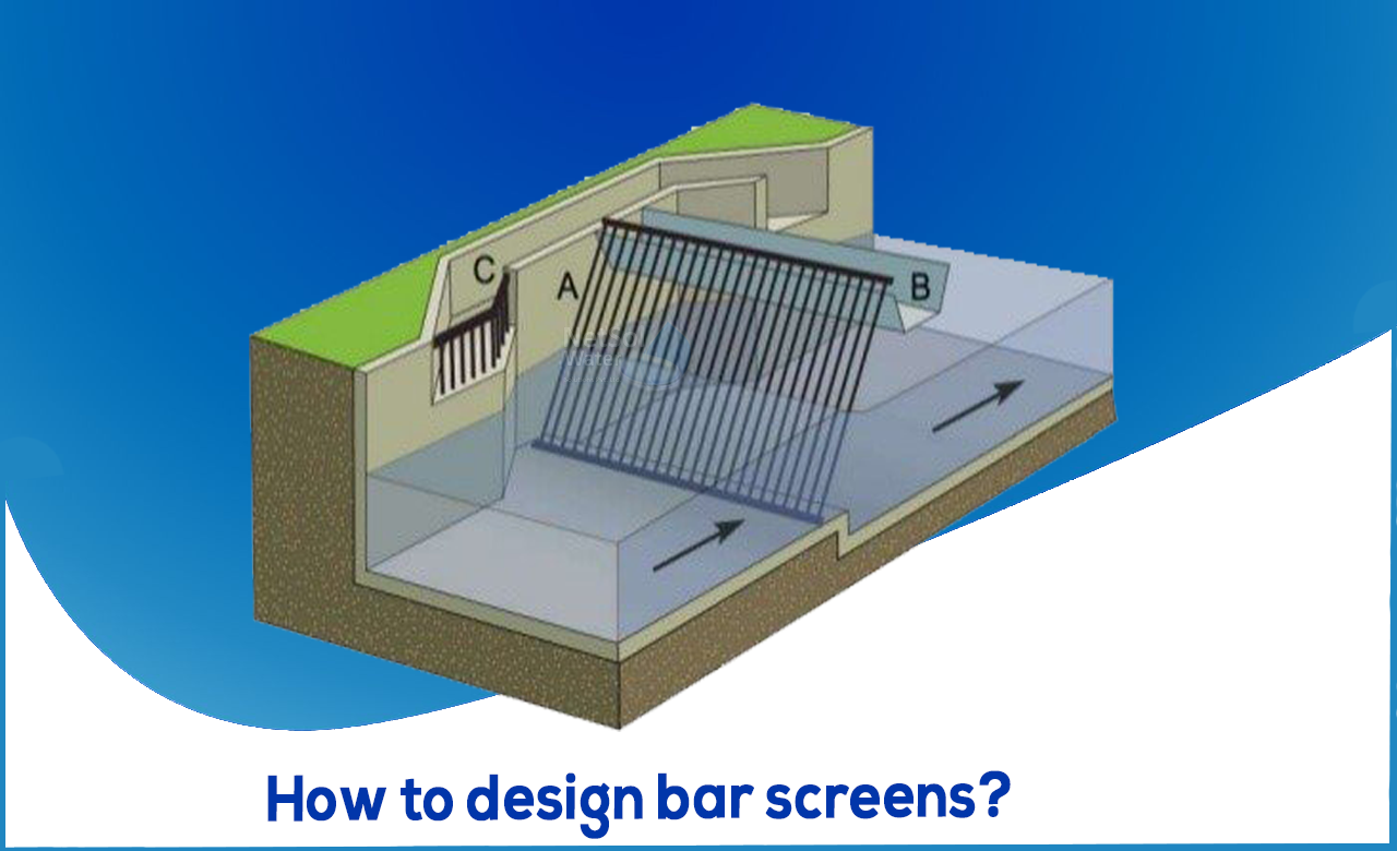
What are bar screens?
In wastewater treatment, screens are used to filter out coarse materials. At wastewater treatment plants, screening is the first unit activity. To minimise damage and clogging of downstream equipment, pipelines, and appurtenances, screening eliminates items such as rags, paper, plastics, and metals. Coarse and fine screens are used in some modern wastewater treatment systems. Screens are of two types:
a). Coarse Screens
Coarse screens have typically apertures of 6 mm (0.25 in) or bigger and remove heavy particles, rags, and trash from wastewater. Mechanically and manually cleaned bar screens, as well as trash racks, are examples of coarse screens.
b). Fine screens
Fine screens are commonly employed to eliminate particles that could cause difficulties in downstream processes, especially in systems that don't have primary treatment. Fine screens typically have openings ranging from 1.5 to 6 mm (0.06 to 0.25 in).
After coarse or fine screens, very fine screens with apertures of 0.2 to 1.5 mm (0.01 to 0.06 in) can reduce suspended particles to values similar to those produced by primary clarifying.
Design considerations for bar screens or bar racks:
(i) Minimum bar size = 10 mm x 50 mm
(ii) Clear spacing between bars = 15 mm to 75 mm
(iii) Allowable head loss = 0.15 m
(iv) Minimum approach velocity = 0.3 m/s
(v) Velocity of flow through screen openings= 0.6 m/s to 1.2 m/s
(vi) Slope with horizontal-
(a) Manually cleaned = 45° to 60°
(b) Mechanically cleaned = 60° to 90°
Design of bar screens:
Step wise calculation of following quantities is presented as:
- 1. Cross section of bar screens
The continuity equation is used to calculate the cross section of the bar screen channel:
Qd = AcVa
Ac= Qd / Va
Qd = design flow in m3 /s, Va = Velocity in the approach channel in m/s, W= channel width in m, d = water depth in the channel in m, Ac = channel cross section in m2
Usually, rectangular channels are used, and the ratio between depth and width is taken as 1.5 to give the most efficient section: d/W = 1.5
- 2. The head loss through the screens is given as
HI = (V2b – Va2) / 2g * 1/ 0.7
HI = head loss, Va = approach velocity, m/s, Vb = Velocity through the openings in m/s,
g = acceleration due to gravity, m/s2
- 3. Cross section of the bar screen is given by following equation
As = Ac / sinq
As = bar screen cross section, m2, q = inclination angle of the screen.
- 4. Net area of the bar screen available for flow is given by the following equation
Anet = AS *(S / S + tbar)
S = space between bars in m, tbar= thickness of the screen bars in m
- 5. Number of bars in the screen is given by the following equation
n tbar + (n-1)S = W
Following all the steps provided above, one can easily go into the designing of bar screens.
The author of the blog is associated with Netsol Water, which is into Effluent Treatment Plant manufacturing, Sewage Treatment Plant manufacturing, and Water Treatment Plants. For more information, consult Netsol water Solutions!


