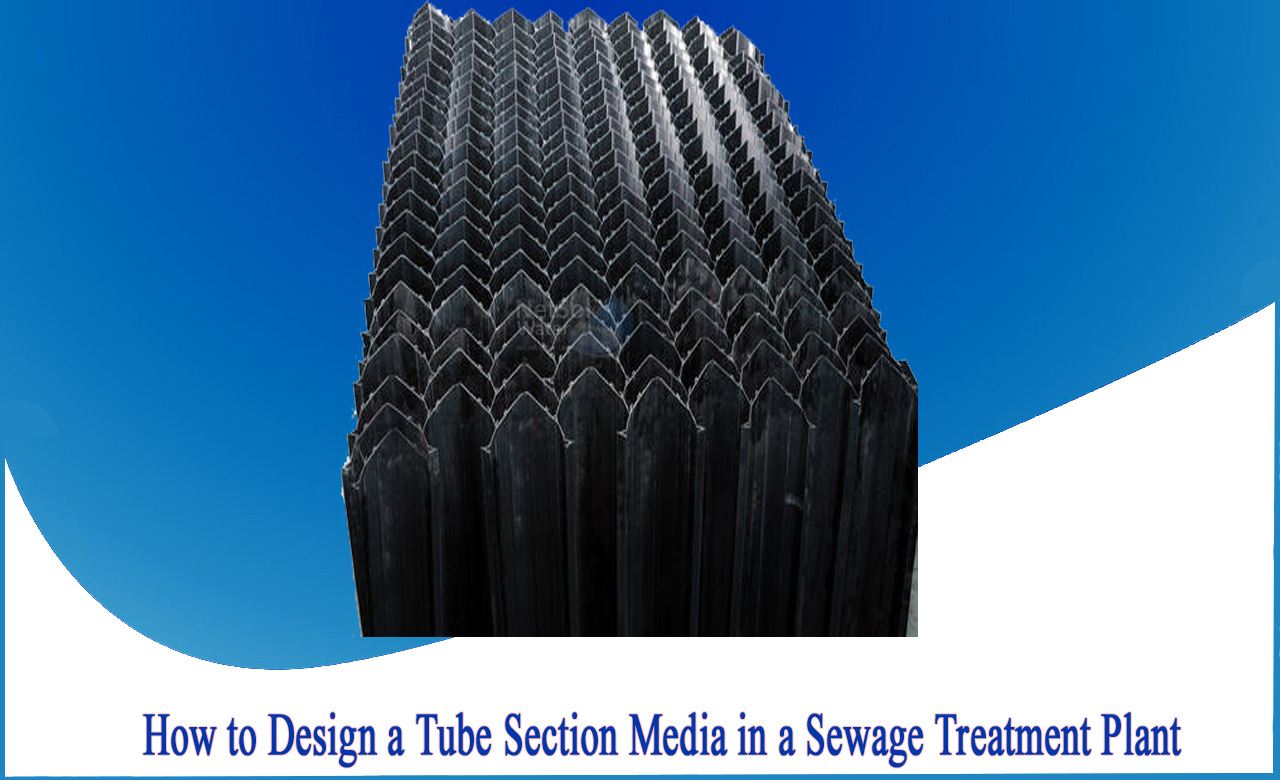
How to design a tube section media in a sewage treatment plant?
Tube clarifiers increase the sedimentation capacity of circular clarifiers and, or rectangular sedimentation tanks by reducing the vertical distance that flake particles must settle before agglomerating into larger particles. The pipe settler uses multiple tubular channels that are tilted side by side at a 60 ° angle, which together form an effective settling area. This ensures a significantly shallower particle sedimentation depth than traditional clarifier sedimentation depths and reduces sedimentation time.
Tube-Settlers catch the settling fine flocs escaping from the purification zone under the Tube-Settlers, allowing larger flakes to reach the bottom of the tank.The spreader channel collects solids and compacts it.In the next step it slides the solids into the tube channel.
What are Tube Settlers?
Tube settlers offer a not so expensive method of upgrading existing water treatment plant clarifiers and sedimentation basins to improve performance. They can also reduce the footprint required in new installations or improve the performance.
It is made up of lightweight PVC. Tube settlers can be easily supported with minimal structures that often incorporate the effluent trough supports. They are available in different modules of different sizes and tube lengths to fit any tank geometry, with custom design and engineering offered by the manufacturer.
Tube Settler Benefits
The benefits of tube clarifiers can be applied to new or existing clarifiers:
>A clarifier tank with a tube clarifier can operate at 2-4 times the normal capacity of a clarifier without a tube clarifier.
>The dose of coagulant can be reduced by up to half while keeping the turbidity at the entrance to the filter in the sewage treatment plant low.
>Less backwashing of the filter means significant savings in both water and electricity operating costs.
>Due to the improved fluidity, new equipment using pipe settler can be designed smaller.
Typical Design of a tube section media
1) Designing a filter media:
Q avg. = 0.694 m3/s = 2,498.4 m3/h
Using the flow of the filter:
Q filter =7 m3 /h/m
Assume,
Area of the filter bed = 356.9 m2= 357 m2
If we use total of 10 filter units used,
Area of one filter unit is obtained by A = 357/10 = 35.7 m.
Assume,
Width= 4.5 m (of one filter unit)
Therefore,
Length = 35.7/4.5 = 7.93 m (say 8 m length and 4.5 wide, A = 36 m)
Checking filtration rate:
Total Area = 4.5 m × 8 m × 10= 360 m2.
Filtration rate, is ok
2) Designing of laterals and manifold:
Using the size of the openings at 6 or 12 mm
For perforation with “d” of 12 mm = 0.0001131 m
Total area of perforations = 0.3% × 36 m = 0.108 m
Total area of laterals = 2 × 0.108 m = 0.216 m
Spacing between laterals = 20 cm
To find the numbers of the lateral,
Total number of the laterals per unit = 2 × 40 = 80
Area per lateral = 0.216 m/80 = 0.0027 m2
Diameter of lateral = 0.0586 m= 5 cm
Numbers of perforations = 0.108 m/0.0001131 m = 954.90= say 960
Use,
Numbers of perforations per lateral
= 960/80 = 12 Numbers/lateral
The total area of the manifold = 2 × Area of the lateral = 2 × 0.216 m = 0.432 m2
Diameter of manifold = 0.742 m, say 75 cm
Total length of the lateral = 450 − (2 × 17 + 5 + 2 × 3.5) = 404 cm
Length of each lateral = 404/4 = 101 cm
For more information, consult Netsol water.


