High wastewater levels in nations with year-round warm temperatures enable and favour, anaerobic treatment of the entire sewage flow, not just the sludge portion. Aerobic treatments require an energy-intensive aeration system, but anaerobic treatment systems like UASB can be built considerably more easily.
Let’s understand the construction of UASB in STPs!
Components of UASB (Up-flow anaerobic sludge blanket) reactor
Three major components make up the UASB reactor:
(a) A sludge bed
(b) Blanket made of sludge
c) The reactor's top-mounted three-phase separator (GLS separator, for gas-liquid-solid separation).
The three-phase separator enables the reactor to separate mixtures of gas, water, and sludge, even when there is significant turbulence.
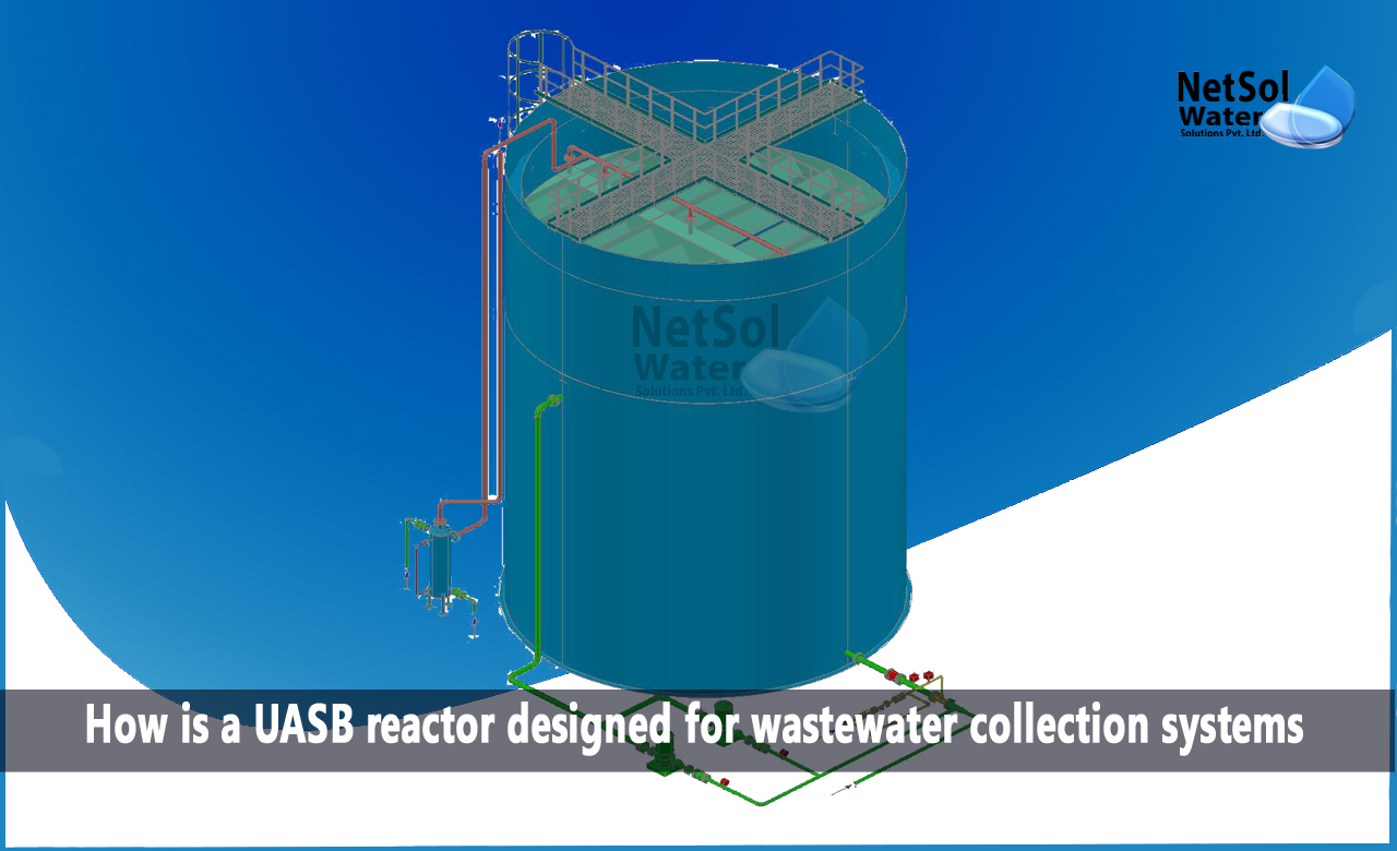
How is a UASB reactor designed for wastewater collection systems?
The UASB reactor is made out of a circular or rectangular tank, where wastewater is forced upwards through a thick layer of sludge that is very anaerobically active. The sludge bed, which makes up roughly half of the reactor's volume, is made up of flocs or microbial granules with a diameter of 1 to 3 mm.
Without using any machinery, the sludge is blended by rising bubbles. The top of the tank, above the sloping walls, is where the cleaned sewage is removed. From very granular and dense particles near the bottom of the reactor, to more dispersed and light particles near the top, the solids profile varies.
The right set of operational parameters must be chosen for the design, including organic concentration, superficial liquid up-flow velocity, reactor volume, sewage collecting system, feed intake system design, hydraulic retention time, etc.
Sewage collection system
The sewage must leave the UASB reactor through a network of launders spread out over the facility, with the main launder situated at the reactor's edge. The secondary settling tank design criterion can be met by designing the sewage launders, so that the weir loading does not exceed it.
The launders should be at least 0.20 m wide to make maintenance simpler. The depth of the wash can be calculated using open channel flow. An additional depth of 0.10 to 0.15 m should be provided to allow free flow.
Later, both sides of the washers must have "V" notches. The 'V' notches in sewage launders are guarded against clogging, when scum baffles are introduced because the baffles catch the floating debris. Scum and sludge may accumulate at the reactor's top. Because, of the accumulation that could develop in the washer, it's important to clean the washers frequently and get rid of the build-up.
Insight into feed inlet system: Intake distribution system in STPs
In order to prevent wastewater from flowing through the sludge bed, and to maintain good contact between the sludge available inside the reactor, and the wastewater introduced, both are crucial.
Thus, it is necessary to develop an adequate intake distribution system. Gravity feed from the top (recommended for wastewater with a high suspended percentage), or pumped feed from the bottom through manifold and laterals (preferred for soluble industrial wastewaters) could be offered, depending on terrain, pumping arrangement, and the risk of inlet pipe clogging.
When processing partially soluble wastewater, in particular, nozzle blockage can be a serious problem, leading to uneven results and sewage dispersion across reactor bottom wastewater. So, it is necessary to create plants for cleaning or flushing the intake system.
How can we assist?
Netsol Water is a top manufacturer of wastewater treatment facilities, and industrial and commercial water treatment facilities in India. Our WWTPs and ETPs effectively eliminate all kinds of chemical, physical, and biological pollutants, with the help of our advanced treatment systems.
We have become a leading manufacturer of sewage treatment plants, by providing the best materials and best construction of UASB, and have created and implemented advanced technologies in a wide range of industries.
Contact us at +91 9650608473 or enquiry@netsolwater.com for expert advice.


