

Designing a 1000 LPH EDI system for a Pharma manufacturing unit
Electrodeionization (EDI) is an advanced water treatment process that utilizes ion exchange and electrochemical principles to remove dissolved impurities from water. In pharmaceutical manufacturing, high-quality water is essential to maintain product integrity and purity. Thus, the design of an EDI system becomes crucial to ensure the production of ultra-pure water.
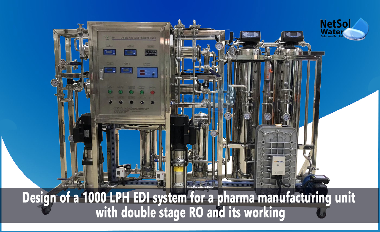
Here we will outline the design of a 1000 LPH EDI system for a pharma manufacturing unit with double-stage reverse osmosis (RO) and its working functions.
Design of 1000 LPH EDI System:
The design of EDI system involves three stages: pre-treatment, double-stage RO, and EDI.
The pre-treatment stage removes large particulate matter, organic matter, and chlorine from the feedwater. The double-stage RO stage further removes dissolved solids from the feedwater, resulting in a product water quality of less than 10 ppm total dissolved solids (TDS). Finally, the EDI stage uses ion exchange membranes and an electrical field to remove remaining impurities and produce ultra-pure water.
Stages:
The stages are as follows:
1. Pre-treatment Stage:
Th e pre-treatment stage includes the following processes:
a. Sand Filter:
A sand filter is used to remove large particulate matter, such as sand, silt, and rust, from the feedwater. The sand filter's design is based on the flow rate, filter media size, and filter bed depth. The formula used to determine the sand filter's surface area is:
Surface Area = Flow Rate x Filtration Rate / ( 60 x 24 x Bed Depth )
Where:
Flow Rate = 1000 LPH
Filtration Rate = 15 m³/h/m²
Bed Depth = 1.2 meters
Thus, the sand filter's surface area is 12.5 m².
b. Activated Carbon Filter:
An activated carbon filter is used to remove organic matter and chlorine from the feedwater. The activated carbon filter's design is based on the flow rate, contact time, and carbon bed depth. The formula used to determine the activated carbon filter's surface area is:
Surface Area = Flow Rate x Contact Time / (Bed Depth x 60)
Where:
Flow Rate = 1000 LPH
Contact Time = 10 minutes
Bed Depth = 0.9 meters
Thus, the activated carbon filter's surface area is 11.1 m².
2. Double-Stage RO Stage:
The double-stage RO stage includes the following processes:
a. First-Stage RO:
The first-stage RO system removes up to 90% of the feedwater's TDS. The design of the first-stage RO system is based on the feedwater's TDS and recovery rate. The formula used to determine the first-stage RO system's membrane area is:
Membrane Area = Flow Rate x TDS / (Recovery Rate x Salt Rejection x 1000)
Where:
Flow Rate = 1000 LPH
TDS = 2000 ppm
Recovery Rate = 75%
Salt Rejection = 98%
Thus, the first-stage RO system's membrane area is 44.8 m².
b. Second-Stage RO:
The second-stage RO system removes up to 98% of the feedwater's TDS. The design of the second-stage RO system is based on the feedwater's TDS and recovery rate. The formula used to determine the second-stage RO system's membrane area is:
Membrane Area = Flow Rate x TDS / (Recovery Rate x Salt Rejection x 1000)
Where:
Flow Rate = 1000 LPH
TDS = 200 ppm
Recovery Rate = 75%
Salt Rejection = 98%
Thus, the second-stage RO system's membrane area is 448 m².
3. EDI Stage:
The EDI stage includes the following processes:
a. Cation Exchange Membrane:
The cation exchange membrane removes cations, such as calcium, magnesium, and sodium, from the feedwater. The design of the cation exchange membrane is based on the feedwater's conductivity and flow rate. The formula used to determine the cation exchange membrane's surface area is:
Surface Area = Flow Rate x Conductivity / (Current Density x Faraday Constant x
Cation Exchange Capacity)
Where:
Flow Rate = 1000 LPH
Conductivity = 0.1 µS/cm
Current Density = 1.5 A/m²
Faraday Constant = 96500 C/mol
Cation Exchange Capacity = 1.8 eq/L
Thus, the cation exchange membrane's surface area is 2.31 m².
b. Anion Exchange Membrane:
The anion exchange membrane removes anions, such as chloride, sulfate, and nitrate, from the feedwater. The design of the anion exchange membrane is based on the feedwater's conductivity and flow rate. The formula used to determine the anion exchange membrane's surface area is:
Surface Area = Flow Rate x Conductivity / (Current Density x Faraday Constant x Anion Exchange Capacity)
Where:
Flow Rate = 1000 LPH
Conductivity = 0.1 µS/cm
Current Density = 1.5 A/m²
Faraday Constant = 96500 C/mol
Anion Exchange Capacity = 1.2 eq/L
Thus, the anion exchange membrane's surface area is 3.47 m².
Working Function of 1000 LPH EDI System:
The 1000 LPH EDI system with double-stage RO operates as follows:
1. Feedwater enters the pre-treatment stage, where sand and activated carbon filters remove particulate matter, organic matter, and chlorine.
2. The pre-treated water enters the first-stage RO, where a semi-permeable membrane removes up to 90% of the feedwater's TDS.
3. The first-stage RO permeate then enters the second-stage RO, where a semi-permeable membrane removes up to 98% of the feedwater's remaining TDS.
4. The second-stage RO permeate then enters the EDI stage, where cation and anion exchange membranes and an electrical field remove remaining impurities and produce ultra-pure water.
5. The ultra-pure water is stored in a product water tank and used in pharmaceutical manufacturing processes.
Summary:
Thus the design of a 1000 LPH EDI system for a pharma manufacturing unit with double-stage RO involves pre-treatment, double-stage RO, and EDI stages. The pre-treatment stage removes large particulate matter, organic matter, and chlorine. The double-stage RO stage removes dissolved solids, and the EDI stage removes remaining impurities to produce ultra-pure water. The EDI system's working function involves passing feedwater through pre-treatment, first-stage RO, second-stage RO, and EDI stages to produce ultra-pure water. The formulae used to determine the system's design parameters are based on the feedwater's properties, flow rate, and recovery rate. The designed 1000 LPH EDI system with double-stage RO is ideal for producing high-quality water in pharmaceutical manufacturing.
Leading manufacturer of sewage treatment plants in India.
Netsol Water is the leading manufacturer, supplier, and exporter of a quality selection of water treatment, and wastewater treatment products in India, by using advanced sewage treatment methods.
RO plants, water softeners, ETPs, STPs, DM plants, AMC, O&M, Ultra filtration, UV, Ozonation, ZLD plants, Anoxic tanks, and other goods and services are available from us. We also provide services to businesses in sectors including automotive, pharmaceutical, textile, pulp & paper, beverages, refineries, schools, hospitals, office buildings, and hotels, among others.
Call us at +91 9650608473 or email at enquiry@netsolwater.com for further information