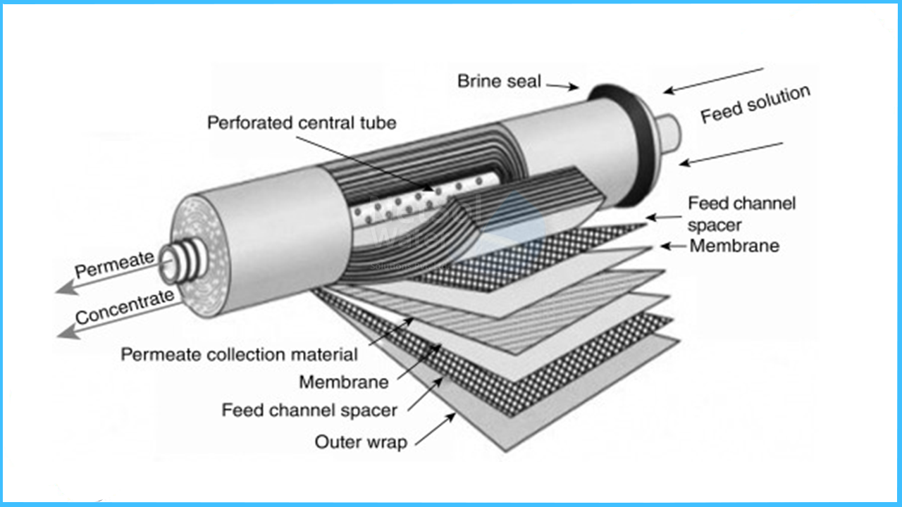
Reverse osmosis (RO) and Nano-filitration (NF) membranes are commonly used as a filtration method to remove many types of dissolved solids (large molecules and ions) from solutions by applying pressure to the solution when it is on one side of a selective membrane. The result is that the solute is retained on the pressurized side of the membrane and the pure solvent is allowed to pass to the other side.
Osmosis occurs when two solutions with different concentrations are separated by a semipermeable membrane. In RO water purification systems, the osmotic pressure is overcome using hydraulic pressure, which is applied using a pump to the concentrated side. Water is then driven from the concentrated solution and collected downstream of the membrane.RO membranes are sized on their water volume production rate and the desired hourly or daily rate of water to be used.
Most commonly used RO membranes are typically composed by a thin film composite membrane consisting of three layers: a polyester support web, a micro porous polysulfone interlayer and an ultra-thin polyamide barrier layer on the top surface.
Schematic cross-section of a thin film composite membrane
Thin film composite membranes are packed in a spiral wound configuration. Such element contains from one to more than 30 sheets, depending on the element diameter and element type. In membrane systems the elements are placed in series inside of a pressure vessel.
The concentrate of the first element becomes the feed to the second element and so on. The permeate tubes are connected with interconnectors (also called coupler), and the combined total permeate exits the pressure vessel at one side of the vessel.
Construction of a spiral wound TFC RO element
The membranes are wound around a perforated permeate pipe.Two membrane sheets are glued together on three sides, only with an opening towards the permeate pipe. The feed water flows across the membrane surface from one side to the other. Due to the high pressure in the vessel, a part of the water penetrates the membrane and this permeate water can only leave the PV through the permeate pipe, while the rest of the water - now more concentrated - leaves on the other side of the membrane , just flowing across the sheet.
LET’S KEEP IN MIND THE FOLLOWING!
The membrane construction for sea water desalination is pretty difficult and needs ample amount of knowledge about the RO process. Some of the key factors to keep in mind while designing or constructing a membrane for the process are-
- 1. RO requires forcing the sea water through progressively smaller membranes
- 2. It also requires a lot of energy for pumping. It's obvious that the massive amounts of energy used in desalination contribute to climate change-causing greenhouse gas emissions, possibly exacerbating the local drought conditions that require use of desalination in the first place.
- 3. On the outlet side, the effluent of desalination plants is brine that is far too salty for the marine life that it comes into contact with. Some desalination plants create sea salt for additional revenue, eliminating the need for any effluent. Another solution is to dilute the brine with the cooling water of a nearby power plant, or just with ocean water.
- 4. All desalination processes produce large quantities of a concentrate, which may be increased in temperature, and contain residues of pre-treatment and cleaning chemicals, their reaction by-products, and heavy metals due to corrosion.


