

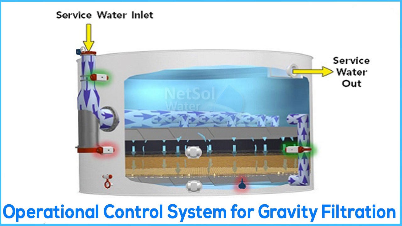
This system uses a cell on the filter's effluent or discharge to control the rate of treatment. A flow-sensing device, a rate controller, and a modulating valve are the most basic components. Direct reading meter systems and indirect reading systems such as venturi or orifice plates are among the flow-sensing devices that can be used.
The rate control design is also highly variable, depending on the flow-sensing device and modulating valve configuration. Pneumatic, electric, mechanical, or a combination of these signals may come from the flow sensor, rate controller, and valve. During operation, the flow-sensing device is employed to determine the flow rate through the filter effluent line. The flow rate is measured and sent to the rate controller, which compares it to an operator-adjustable set point. If the measured and set-point flow rates differ, the controller sends the modulating valve an appropriate signal to open or close, aligning the measured and set-point flow rates. The real head loss across the filter is substantially smaller than the available head loss when a filter run begins immediately after backwash. The available head loss can be broken down into two categories: clean-bed head loss and dirt head loss. The fixed elements of the filter system, as well as hydraulic losses through the media, under drain, and piping system, make up clean-bed head loss. The pressure loss across the filter caused by trapped particles in the filter medium is known as dirt head loss.
The filter system has the least degree of restriction following a backwash, when dirt head loss is at its lowest, if left uncorrected, water will flow at its fastest rate. The modulating valve is closed to generate head loss through the valve to restrict the flow back to the set-point rate in order to control the real rate to the set-point value. The flow regulating valve is gradually opened as the dirt head loss increases to maintain a steady flow rate leaving the filter. The level in the filter cell may change over time, and if time or filtered turbidity don't dictate the frequency, a backwash can be performed when the actual head loss reaches the available head loss across the filter. When the cell water level reaches its maximum elevation and the modulating valve has moved to its full open position, the actual and available head loss equal each other.
Pros
- 1. Despite fluctuations in head loss through the system, the allowable flow rate through a cell is kept constant at the set point at all times.
- 2. An operator can simply manage the maximum flow rate through a single filter cell with effluent rate control systems.
- 3. The continuous treatment rate also prevents collected materials from dislodging within the filter bed, which can lead to breakthrough.
Cons
- 1. The calibration of sensors in effluent rate control systems necessitates the most operator attention. With such systems, overall plant system control is especially crucial to avoid numerous control schemes warring against one another.
- 2. Because the flow to many filters isn't regulated, this form of control lends itself to a start-and-stop operational scheme. This can result in a slug flow scenario, in which a significant initial flow of unclean water slugs the clean filter. A filter-to-waste step is frequently included in the filter to cater for this type of scenario. The effluent valve, not the in flue, stops the unit when a filter is to be put into backwash flow.
If you have any doubts, please feel free to reach us. We can be reached at 9650608473, or feel free to leave your query at enquiry@netsolwater.com.
Netsol Water Solution is a Greater Noida, Uttar Pradesh, India based manufacturer, seller, and supplier of waste and wastewater treatment plant. With the latest and leading technology, we are the leader Commercial RO Plant Manufacturer, Industrial RO Manufacturer, Sewage Treatment Plant Manufacturer, Effluent Treatment Plant.