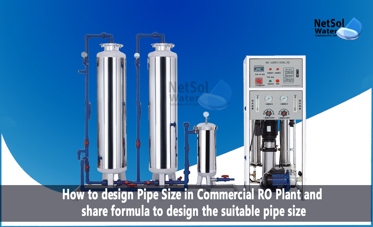
How to design Pipe Size in Commercial RO Plant?
Commercial reverse osmosis (RO) plants are essential for producing clean and safe drinking water for industrial and commercial applications. One important aspect of designing a commercial RO plant is selecting the right pipe size. The pipe size affects the overall efficiency of the system, and selecting the correct size is crucial for maintaining adequate water flow rates and minimizing pressure losses.
Here, we will discuss how to design pipe size in a commercial RO plant, along with the formula calculations required for a 500 and 1000 LPH RO plant.
Step 1: Determine the Required Flow Rate
The first step in designing the pipe size for a commercial RO plant is to determine the required flow rate. This is calculated based on the production capacity of the RO plant, which in this case is 500 and 1000 liters per hour (LPH).
Step 2: Determine the Friction Loss
Friction loss is the pressure drop that occurs due to the flow of water through pipes. It is essential to consider the friction loss while designing the pipe network in the RO plant. The friction loss can be calculated using the following formula:
Friction Loss = [(Flow Rate x Pipe Length) / (Pipe Diameter^5)] x [150 / (Pipe Roughness^0.5)]
Where, Flow Rate = Required flow rate in liters per hour Pipe Length = Total length of pipe in meters Pipe Diameter = Internal diameter of pipe in millimeters Pipe Roughness = Roughness coefficient of the pipe material (for PVC, it is 0.007)
Step 3: Determine the Allowable Pressure Drop
The allowable pressure drop is the maximum pressure drop that is acceptable for the RO plant to function properly. The allowable pressure drop is typically 10% of the feed water pressure. For example, if the feed water pressure is 3 bar, then the allowable pressure drop would be 0.3 bar.
Step 4: Select the Pipe Size
Once the friction loss and allowable pressure drop have been determined, the pipe size can be selected using the following formula:
Pipe Diameter = [Flow Rate / (Velocity x 3.14 / 4)]^0.5
Where, Flow Rate = Required flow rate in liters per hour Velocity = Flow velocity in meters per second (Typically 1-2 m/s)
For example, let us assume that we need to design the pipe size for a 500 LPH RO plant with a feed water pressure of 3 bar.
Step 1: Required Flow Rate = 500 LPH
Step 2: Friction Loss = [(500 x Pipe Length) / (Pipe Diameter^5)] x [150 / 0.007^0.5] Assuming a pipe length of 10 meters, the friction loss for a 1-inch PVC pipe is 0.2 bar.
Step 3: Allowable Pressure Drop = 10% of 3 bar = 0.3 bar
Step 4: Pipe Diameter = [500 / (1.5 x 3.14 / 4)]^0.5 = 11.5 mm
Hence, for a 500 LPH RO plant with a feed water pressure of 3 bar, a 1-inch PVC pipe with a length of 10 meters and a diameter of 11.5 mm would be suitable.
Similarly, the pipe size can be calculated for a 1000 LPH RO plant or any other capacity using the above formula calculations.
Conclusion:
In conclusion, the design of the pipe size for a commercial RO plant is critical for the efficient operation of the system. By following the steps mentioned above and using the formula calculations, the appropriate pipe size can be determined to ensure optimal performance, reduce pressure drop, and minimize energy consumption.
To get in touch with us and to relish the benefits of our services, call us at +91-9650608473 or send an email to enquiry@netsolwater.com


