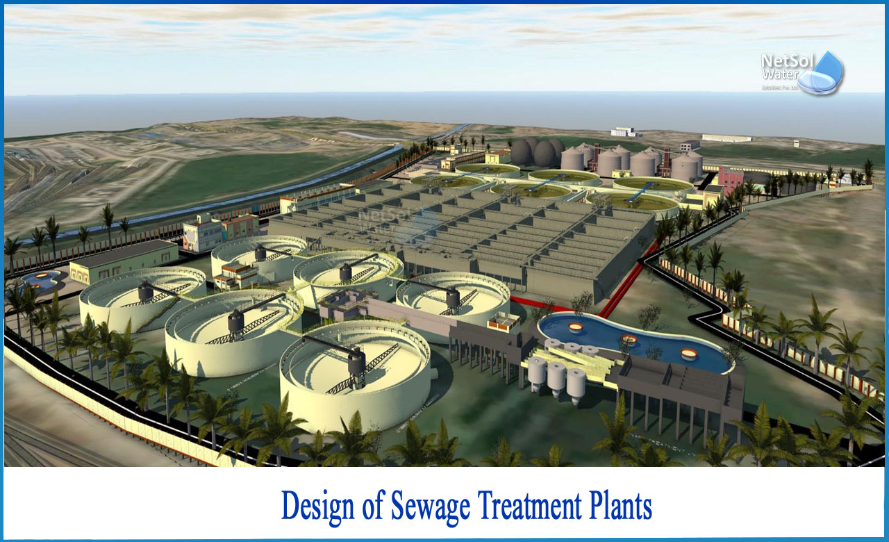
What is sewage treatment?
The process of eliminating pollutants from wastewater and flat sewage, both runoff (effluents) and domestic, is known as sewage treatment.
To eliminate physical, chemical, and biological impurities, it uses physical, chemical, and biological processes. Its goal is to generate a treated effluent and sludge waste suitable for release or re-use in the sewage treatment plant.
How to design of Sewage Treatment Plants?
Sewage refers to the wastewater from a populated region. Before being released into the water body or otherwise disposed of without threatening public health or generating objectionable circumstances, the liquid wastes will need to be treated.
Layout of sewage treatment plant: Points to consider
Follow?ing points should be kept in mind while giving layout of any sewage treatment plant:
1: All of the plants should be placed in the correct order so that sewage from one process flows immediately to the next.
2: If at all feasible, all of the plants should be built at such an elevation that sewage can only flow from one plant to the next due to gravity.
3: All of the treatment units should be positioned in such a manner that they use the least amount of space possible. This will save money in the long run.
4: A sufficient amount of space should be occupied to allow for future expansion.
5: Staff quarters and offices should also be located near the treatment plant so that operators can keep a close eye on it.
6: The treatment plant site should be well-kept and presentable.
Considerations for the design
Du?ring the design of a sewage treatment unit, the following factors are taken into account:
1: The planning term should be between 25 and 30 years.
2: The design should be based on the average residential flow rather than the hourly sewage flow.
3: Instead of supplying one large unit for each treatment, more than two tiny units should be given, allowing the plant to remain operational while undergoing maintenance and repair.
4: If required, overflow weirs and bypasses should be supplied to cut the specific process.
5: At every location and step, self-cleaning velocity should increase.
6: The treatment units should be designed to be cost-effective, as well as easy to maintain and operate.
Land Area of the STP
Population densities have risen in recent years. Even public lands are being encroached upon, making it harder to get rid of them. As a result, obtaining large open land tracts for the construction of STPs is a challenge. Furthermore, even if open spaces are accessible, because to densification, the populace is extremely close to these lands and objects to the STPs nearby. As a result, STPs must be designed to take up less space than previous STPs.
Rise of Multi-tier STPs
This has given rise to the notion of multi-tier STPs, in which the primary clarifier is located on the top level, with the aeration tank underneath it and the secondary clarifier on the bottom floor.
Multi-tier STPs, such as the SBR-based STP, can also be built, reducing the amount of land required. MBR, on the other hand, results in a smaller area due to increased MLSS concentration and a smaller volume of aeration tanks, allowing tanks to be stacked vertically. The necessity for 4.5 m of headroom between the top of the lower tank's walls and the roof of the higher tank is a significant engineering requirement in such instances.
This is due to the fact that these places are classified as industrial and include electrical utilities.In such circumstances, the recurrent expense of pumping all of the raw sewage over the full increased height must be considered.
In a STP, the treatment units are arranged in a certain order-
The guidelines for the ideal configuration will be as follows:
• Common walls can be used to integrate the civil construction of units, particularly sewage holding facilities.
• This might be circular tanks inscribed concentrically or rectangular or square tanks contacting each other.
• Because sewage may be transported by channels through all such units, this will save money on pipe.
• Stop gates controlled by hand wheels on a rack and pinion systems can be used to replace expensive hidden valves and alleviate the difficulties of maintaining them.
Around the STPs, there is a buffer zone!
Screen chambers, grit chambers, primary clarifiers, sludge thickening and dewatering units are among the STP equipment’s that require deodorization.
However, owing to in-situ aerobic digestion of sludge, odour emissions from sludge treatment plants with extended aeration systems are insignificant. Specific buffer zones are not necessary if STPs are equipped with deodorization systems.
In the event of STPs where a deodorization system is not available, a distance of 100 meters between the odour-producing units and the habitation is advised. However, by holding a public consultation, this distance can be narrowed.
Engineering Data Required
The following information is required:
a) Contour map and elevations related to the nearest permanent Bench Mark of the Survey of India.
b) Soil tests till hard stratum is reached, then test bores in a grid of 500 m squares.
c) Rainfall for at least 50 years at the closest observatory.
d) Rainfall with the highest intensity.
e) The region's earthquake records.
f) Maximum flood level at the site as well as in the designated receiving water.
Mechanical Equipment Installation
The GA drawing is the general arrangement (GA) drawing of each mechanical equipment placed in its civil works tank. These drawings must clearly depict how the bolts, nuts, and other fasteners are secured in the civil works. It's preferable if the drawing specifies the procedure for removing the equipment later on, if necessary. It will serve as the foundation for the installation of the equipment.
Before being installed on site, all steel pieces must be sandblasted and then coated with the authorized primer and first coat. Before allowing the erection, all purchased equipment pieces must be thoroughly inspected on site for scratches and paint peeling.Overflow weir edges must be levelled by directing the final levels with two levelling instruments that are perpendicular to each other and focus on the same reference at the same time.
Mechanical equipment should be run first, followed by electrical prime movers, and should not be run for excessively extended periods of time. The building of the sludge scrapper in clarifiers, as well as the screeding of the inclined floor, must be finished.
Bypasses for Units
Gravity bypass procedures must be used, either a direct outfall conduit or a separate terminal tank prior to the outfall conduit. A tank's volume must be equal to the buffer volume required, as determined using the mass diagram.
Before making a selection, however, the economics of a specialized terminal tank vs. the capacity of the outfall conduit to manage peak flow must be examined. This volume should be able to be chlorinated to the same level as treated sewage before being discharged. If RCC pipes or conduits are utilized, they must be protected with High Alumina cement or a sulphate-resistant cement.
Other pipe materials or brick masonry conduit can also be used. All such pipelines or conduits must be constructed at a velocity of at least 0.6 m/s and at most 2.5 m/sec. After each location, a bypass facility will be supplied as a screen chamber, detritor, and main clarifier.
Because the MLSS will be rinsed out, there will be no bypass before the secondary clarifiers of activated sludge plants. The chlorinator should be able to withstand a 10 mg/L dose. Based on the typical flow, the chlorine contact tank must have a capacity of 30 minutes. Its physical arrangements must be made with the permission of the pollution control authorities and the waterways authority.
Dewatering of the Unit
Because sewage flows 24 hours a day, seven days a week, dewatering of treatment units is not a conventional requirement in STPs.
However, if civil work is required in a tank for maintenance, dewatering is required. All units must have a puddle flange pipe with a minimum ID of 150 mm in the side-wall directly above the formation level, equipped with an isolation valve, and closed on the airside by a detachable blank flange. This flange can be used to attach a portable diesel-powered pump set to pump the contents into the plant bypass chambers.
Because the sidewalls of these chambers in the by-pass pipe-line will be at the same height as the sidewalls of the treatment units, gravity dewatering will not be achievable.
Addressing recent technologies in STP selection
Many organizations have urged implementers in the area to innovate and explore new technologies as well as Public Private Partnership (PPP) models without sacrificing on core technical and financial protections.
STP projects could be developed on a long-term commitment from the private sector partner, either on a PPP/build-own-operate-transfer (BOOT) basis or on an engineering procurement construction (EPC) plus O&M for 15 years, where a portion of the EPC cost is payable over a long-term O&M period, regardless of the technology chosen.


